1-p0803-0861-vf1000_en 55 / 62
10秒後にBOOKのページに移動します
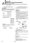
Series VF Specific Product Precautions 2 Plug Connector Lead Wire Length How to Order Connector Assembly DC : V200-30-4A- 100 VAC : V200-30-1A- 200 VAC : V200-30-2AOther AC voltages : V200-30-3AWithout lead wire : V200-30-A (With a connector and 2 sockets) Caution Plug connector lead wires have a standard length of 300 mm, however, the following lengths are also available. How to Order Specify the connector assembly part number together with the part number for the plug connector type solenoid valve without connector. (Example) Lead wire length: 2000 mm DC AC VF3130-5LO1-02 VF3130-1LO1-02 V200-30-4A-20 V200-30-1A-20 Lead wire length Nil 6 10 15 20 25 30 50 300 mm 600 mm 1000 mm 1500 mm 2000 mm 2500 mm 3000 mm 5000 mm How to Use DIN Terminal Connector Connection 1) Loosen the set screw and pull the connector out of the solenoid valve terminal block. 2) After removing the set screw, insert a flat head screwdriver, etc. into the notch on the bottom of the terminal block and pry it open, separating the terminal block and the housing. 3) Loosen the terminal screws on the terminal block, insert the core of the lead wire into the terminal, and attach securely with the terminal screws. In addition, when using the DC mode type with a surge voltage suppressor (polar: S and Z types), connect wires corresponding to the polarity (+ or .) that is printed on the terminal block. 4) Secure the cord by fastening the ground nut. In the case of connecting wires, select cabtire cords carefully because if those out of the specified range (o4.5 to o7) are used, it will not be able to satisfy IP65 (enclosure). Tighten the ground nut and set screw within the specified range of torque. Changing the entry direction After separating the terminal block and housing, the cord entry direction can be changed by attaching the housing in the opposite direction. . Make sure not to damage elements, etc., with the lead wires of the cord. Precautions Plug in and pull out the connector vertically without tilting to one side. Applicable cable Cable O.D.: o4.5 to o7 (Reference) 0.5 mm2 to 1.5 mm2, 2-core or 3-core, equivalent to JIS C 3306 Applicable crimped terminal O terminal: R1.25-4M that is specified in JIS C 2805 Y terminal: 1.25-3L, which is released by JST Mfg. Co., Ltd. Stick terminal: Size 1.5 or shorter The DIN terminal with an IP65 (enclosure) is protected against dust and water, however, it must not be used in water. Caution Be sure to read before handling. Refer to front matter 53 for Safety Instructions, pages 3 to 8 for 3/4/5 Port Solenoid Valves Precautions. . Refer to page 857 for the DIN connector part no. Ground nut Tightening torque 2.5 to 3.75 N・m Washer Grommet (Rubber) Set screw Tightening torque 0.5 to 0.6 N・m Terminal screw 3 locations Tightening torque 0.4 to 0.5 N・m Terminal block (Location for mounting light) (Voltage symbol) . (Polarity indication) Housing A 856