1-p0803-0861-vf1000_en 56 / 62
10秒後にBOOKのページに移動します
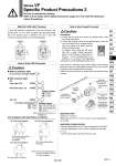
Y type D type 10 11 5.5 8.5 LED R D + . NL R R LED Terminal block cover assembly V200-66-2A Circuit diagram with light (Built-in connector) How to Order DIN Connector Caution 傱 Without indicator light DC, AC, Common to all voltages: V200- -1 傱 With indicator light DC Polar type (𡱖Z) : V200- -3- Non-polar type (𡱖U) : V200- -5- AC (𡱖Z) : V200- -7- Rated voltage 01 02 07 100/110 VAC [115 VAC] 200/220 VAC [230 VAC] 240 VAC Rated voltage 05 06 24 VDC 12 VDC Connector specifications 61 63 D type Y type AC (𡱖Z) circuit diagram DC (𡱖Z) circuit diagram NL: Neon light, R: Resistor LED: Light emitting diode D: Protective diode R: Resistor DC (𡱖U) circuit diagram LED: Light emitting diode R: Resistor DIN (EN175301-803) Terminal Y type DIN terminal corresponds to the DIN connector with terminal pitch 10 mm, which complies with EN175301-803B. Since the terminal pitch is different from the D type DIN connector, these two types are not interchangeable. Set screw Tightening torque 0.5 to 0.6 N・m Terminal block cover Ground terminal screw Tightening torque 0.5 to 0.6 N・m Terminal screw (2 locations) Tightening torque 0.5 to 0.6 N・m Grommet (Rubber) Washer Ground nut Tightening torque 2.5 to 3.75 N・m In the case of connecting wires, select cabtire cords carefully because if those out of the specified range (o4.5 to o7) are used, it will not be able to satisfy IP65 (enclosure). Tighten the ground nut and set screw within the specified range of torque. Applicable cable Cable O.D.: o4.5 to o7 (Reference) 0.5 mm2 to 1.5 mm2, 2-core or 3-core, equivalent to JIS C 3306 Applicable crimped terminal O terminal: Equivalent to R1.25-3 that is specified in JIS C 2805 Y terminal: Equivalent to 1.25-3, which is released by JST Mfg. Co., Ltd. . Use O terminal when a ground terminal is used. (+) (.) Caution How to Use Conduit Terminal Connection 1) Loosen the set screw and remove the terminal block cover from the terminal block. 2) Loosen the terminal screws on the terminal block, insert the core of the lead wire or crimped terminal into the terminal, and attach securely with the terminal screws. In addition, when using the DC mode type with a surge voltage suppressor (polar: S and Z types), connect wires to terminal 1 and 2 corresponding to the polarity (+ or .) as shown on the right figure. 3) Secure the cord by fastening the ground nut. Note) The 24 VAC specification is the same as those in the DC (𡱖U) circuit diagram. Note) For 24 VAC, the part no. is V200-61-5-B. 63 Be sure to read before handling. Refer to front matter 53 for Safety Instructions, pages 3 to 8 for 3/4/5 Port Solenoid Valves Precautions. Series VF Specific Product Precautions 3 857 SY SJ SY SV SYJ SZ VF VP4 S0700 VQ VQ4 VQ5 VQC VQC4 VQZ SQ VFS VFR VQ7 A