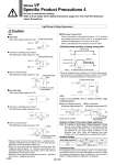
Black (.) Red (+) Polarity protection diode Diode Diode Coil Coil Coil Coil Coil Coil Diode LED Polarity protection diode Black (.) Red (+) (.) For DIN type, installed in the connector LED Polarity protection diode (+) Varistor (., +) (+, .) (., +) (+, .) (., +) (+, .) Varistor LED For DIN type, installed in the connector Varistor LED Polarity protection diode (.) (+) LED Varistor LED (~) (~) (~) (~) For DIN type, installed in the connector NL: Neon light NL Note) Varistor Coil Coil Coil Diode PWM circuit Applied voltage Standard With power saving circuit 24 V 0 V 0 W 40 ms 1.55 W (1.75 W) 0.55 W (0.75 W) Note) ( ) : For DIN terminal (D), Conduit terminal. Light/Surge Voltage Suppressor Caution . Please connect correctly the lead wires to + (positive) and . (negative) indications on the connector. (For non-polar type, the lead wires can be connected to either one.) . When the valve with polarity protection diode is used, the voltage will drop by approx. 1 V. Therefore, pay attention to the allowable voltage fluctuation (For details, refer to the solenoid specifications of each type of valve). . Solenoids, whose lead wires have been pre-wired: + (positive) side red and . (negative) side black. ūé Polar type With surge voltage suppressor (ūģS) ūé Non-polar type With surge voltage suppressor (ūģR) ūĎ Grommet or L/M-type plug connector With light/surge voltage suppressor (ūģU) ūĎ Grommet or L/M-type plug connector With light/surge voltage suppressor (ūģZ) ūĎ DIN or Conduit terminal With light/surge voltage suppressor (ūģZ) ūĎ DIN or Conduit terminal With light/surge voltage suppressor (ūģU) Residual voltage of the surge voltage suppressor Note) If a varistor or diode surge voltage suppressor is used, there is some residual voltage to the protection element and rated voltage. Therefore, refer to the table below and pay attention to the surge voltage protection on the controller side. Also, since the response time does change, refer to the specifications on pages 809 and 823. Continuous Duty For applications such as mounting a valve on a control panel, incorporate measure to limit the heat radiation so that it is within the operating temperature range. Furthermore, do not touch it while it is being energized or right after it is energized. Residual Voltage Surge voltage suppressor S, Z R, U DC 24 V Approx. 47 V Approx. 1 V Approx. 1 V . 12 V Approx. 32 V AC S type is not available, since a rectifier prevents surge voltage generation. ūĎ Grommet or L/M-type plug connector With light/surge voltage suppressor (ūģZ) ūĎ DIN or Conduit terminal With light/surge voltage suppressor (ūģZ) Note) LED for 24 VAC. ūé With power saving circuit Power consumption is decreased by approx. 1/3 by reducing the wattage required to hold the valve in an energized state. (Effective energizing time is over 40 ms at 24 VDC.) Refer to the electrical power waveform as shown below. . Since the voltage will drop by approx. 0.5 V due to the transistor, pay attention to the allowable voltage fluctuation. (For details, refer to the solenoid specifications of each type of valve.) Be sure to read before handling. Refer to front matter 53 for Safety Instructions, pages 3 to 8 for 3/4/5 Port Solenoid Valves Precautions. Series VF Specific Product Precautions 4 A 858