1-p0803-0861-vf1000_en 59 / 62
10秒後にBOOKのページに移動します
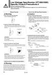
Manual Override Warning Caution 1. Connector attachment/detachment . To attach a connector, hold the lever and connector unit between your fingers and insert straight onto the pins of the solenoid valve so that the lever’s pawl is pushed into the groove and locks. . To detach a connector, remove the pawl from the groove by pushing the lever downward with your thumb, and pull the connector straight out. How to Use L/M-Type Plug Connector Lead wire Cover Groove Pin Cover Groove Pin Connector Lever DC polarity indication Hook Socket Part no. DXT170-71-1 +- Be sure to read before handling. Refer to front matter 53 for Safety Instructions, pages 3 to 8 for 3/4/5 Port Solenoid Valves Precautions. Low Wattage Specification (VF1000/3000) Specific Product Precautions 6 1. Non-locking push type [Standard] Press in the direction of the arrow. 2. Push-turn locking slotted type [D type] 3. Push-turn locking lever type [E type] Locked position Locked position PUSH LOCK PUSH LOCK Caution Caution Solenoid Valve for 200/220 VAC Specification AC specification solenoid valves with grommet or L/M-type plug connector have a built-in rectifier circuit in the pilot section to operate the DC coil. With 200/220VAC specification pilot valves, this built-in rectifier generates heat when energized. The surface may become hot depending on the energized condition; therefore, do not touch the solenoid valves. Warning 0.2 to 0.33 mm2 Max. cover diameter: o1.7 mm Socket Lead wire Crimping area Core wire crimping area Hook Covering Core wire Connector Lead wire Socket Hook 2. Crimping lead wire and socket connection Strip 3.2 to 3.7 mm at the end of the lead wires, insert the ends of the core wires evenly into the sockets, and then crimp with a crimping tool. When this is done, take care that the coverings of the lead wires do not enter the core wire crimping area. (Please contact SMC for the dedicated crimping tools.) 3. Socket with lead wire attachment/detachment . Attachment Insert the sockets into the square holes of the connector (with +, . indication), and continue to push the sockets all the way in until they lock by hooking into the seats in the connector. (When they are pushed in, their hooks open and they are locked automatically.) Then, confirm that they are locked by pulling lightly on the lead wires. . Detachment To detach a socket from a connector, pull out the lead wire while pressing the socket’s hook with a stick having a thin tip (approx. 1 mm). If the socket will be used again, first spread the hook outward. After pushing down, turn in the direction of the arrow. If it is not turned, it can be operated the same way as the non-locking push type. After pushing down, turn in the direction of the arrow. If it is not turned, it can be operated the same way as the non-locking push type. When locking the manual override with the push-turn locking type (D or E type), be sure to push it down before turning. Turning without first pushing it down can cause damage to the manual override and other trouble such as air leakage, etc. When operating the D type, use a watchmakers’ screwdriver and turn lightly. [Torque: Less than 0.1 N・m] 860