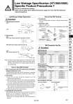
How to Use DIN Terminal 4. Precautions Plug in and pull out the connector vertically without tilting to one side. 5. Applicable cable Cable O.D: o3.5 to o7 (Reference) 0.5 mm2, 2-core or 3-core, equivalent to JIS C 3306 Ground nut Washer Grommet (Rubber) (Voltage symbol) Refer to the table below. Terminal screw (3 locations) Set screw Housing (Location for light mounting) Terminal block Notch Tightening torque 1.65 to 2.5 N・m Tightening torque 0.3 to 0.4 N・m Tightening torque 0.2 to 0.25 N・m Light/Surge Voltage Suppressor Caution 1. L/M-type plug connector 2. DIN terminal With surge voltage suppressor (DS, DOS, YS,YOS) With indicator light (DZ, YZ) With light/surge voltage suppressor (DZ, YZ) Note) If a varistor surge voltage suppressor is used, there is some residual voltage to the protection element and rated voltage. Therefore, pay attention to the surge voltage protection on the controller side. Varistor LED (., +) (+, .) LED Varistor (~) (~) Varistor (., +) (+, .) Varistor Varistor LED (., +) (+, .) NL: Neon light NL (~) (~) How to Use DIN Terminal 1. ISO#: Conforming to EN-175301-803C (former DIN 43650C) (Distance between pins: 8 mm) The DIN terminal type with an IP65 (enclosure) is protected against dust and water, however, it must not be used in water. 2. Connection 1) Loosen the set screw and pull the connector out of the solenoid valve terminal block. 2) After removing the set screw, insert a flat head screwdriver, etc. into the notch on the bottom of the terminal block and pry it open, separating the terminal block and the housing. 3) Loosen the terminal screws (slotted head screw) on the terminal block, insert the core of the lead wire into the terminal according to wiring connection, and attach securely with the terminal screws. 4) Tighten the ground nut to secure the wire. 3. Changing the entry direction After separating the terminal block and housing, the cord entry direction can be changed by attaching the housing in a different direction (four directions at 90° intervals). . Make sure not to damage a light, etc., with the lead wires of the cord. DIN Connector Part No. Circuit diagram with light Rated voltage 24 VDC 12 VDC 100 VAC 200 VAC 110 VAC (115VAC) 220 VAC (230 VAC) With indicator light Voltage symbol 24 V 12 V 100 V 200 V 110 V 220 V Part no. SY100-82-3-05 SY100-82-3-06 SY100-82-2-01 SY100-82-2-02 SY100-82-2-03 SY100-82-2-04 Rated voltage Common to all voltages Without indicator light DIN terminal (D) DIN terminal (Y) Voltage symbol None Part no. SY100-82-1 NL: Neon light R: Resistor LED: Light emitting diode R: Resistor AC circuit diagram DC circuit diagram R LED 1 2 NL R 1 2 Rated voltage 24 VDC 12 VDC 100 VAC 200 VAC 110 VAC 220 VAC Voltage symbol 24 V 12 V 100 V 200 V 110 V 220 V Part no. SY100-61-3-05 SY100-61-3-06 SY100-61-2-01 SY100-61-2-02 SY100-61-2-03 SY100-61-2-04 Without indicator light SY100-61-1 With indicator light Caution Be sure to read before handling. Refer to front matter 53 for Safety Instructions, pages 3 to 8 for 3/4/5 Port Solenoid Valves Precautions. Low Wattage Specification (VF1000/3000) Specific Product Precautions 7 Coil Coil Coil Coil Coil 861 SY SJ SY SV SYJ SZ VF VP4 S0700 VQ VQ4 VQ5 VQC VQC4 VQZ SQ VFS VFR VQ7