1-p1109-1152-vq5000_en 10 / 45
10秒後にBOOKのページに移動します
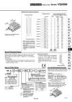
COM. 13 25 SOL.B 12 SOL.A 24 SOL.B 11 SOL.A 23 SOL.B 10 SOL.A 22 SOL.B 9 SOL.A 21 SOL.B 8 SOL.A 20 SOL.B 7 SOL.A 19 SOL.B 6 SOL.A 18 SOL.B 5 SOL.A 17 SOL.B 4 SOL.A 16 SOL.B 3 SOL.A 15 SOL.B 2 SOL.A 14 SOL.B 1 SOL.A VQ 5 Type of actuation Series 1 2 3 4 5 6 Seal 0 1 Coil voltage Manual override Light/Surge voltage suppressor 5 VQ5000 Terminal no. Polarity Standard wiring Electrical wiring specifications 1 0 0 5 1 2 3 4 5 6 Function 25 24 23 14 15 16 17 18 19 20 21 22 12 11 10 1 2 3 4 5 6 7 8 9 13 25 24 23 14 15 16 17 18 19 20 21 22 12 11 10 1 2 3 4 5 6 7 8 9 13 COM 3m Special Wiring Specifications How to Order Valves How to Order Manifold Assembly [Order example] D side U side 1 2 3 ・・・・・・・ Stations Stations are counted starting from the first station on the D side. D-sub connector Connector terminal no. Double wiring (connected to SOL. A and SOL. B) is adopted for the internal wiring of each station, regardless of valve and option types. Mixed single and double wiring is available as a semi-standard specification. For details, refer to below. 1 station 2 stations 3 stations 4 stations 5 stations 6 stations 7 stations 8 stations 9 stations 10 stations 11 stations 12 stations D-sub connector assembly (AXT100-DS25- ) Wire colors 015 030 050 Lead wire color Dot marking (.) (+) Black None (.) (+) Yellow Black (.) (+) Brown None (.) (+) Pink Black (.) (+) Red None (.) (+) Blue White (.) (+) Orange None (.) (+) Purple None (.) (+) Yellow None (.) (+) Gray None (.) (+) Pink None (.) (+) Orange Black (.) (+) Blue None (.) (+) Red White (.) (+) Purple White (.) (+) Brown White (.) (+) Gray Black (.) (+) Pink Red (.) (+) White Black (.) (+) Gray Red (.) (+) White Red (.) (+) Black White (.) (+) Yellow Red (.) (+) White None (+) (.) Orange Red Positive common specifications Note) Negative common specifications Double wiring (connected to SOL. A and SOL. B) is used for the internal wiring of each station regardless of valve and option types. Mixed single and double wiring is available as a semi-standard specification. 1. How to Order Indicate option symbol “-K” in the manifold part number and be sure to specify station positions for single or double wiring on the manifold specification sheet. 2. Wiring specifications Connections begin with the A side solenoid of the first station being connected to terminal no. 1, and continue in the order indicated by the arrows in the drawing without skipping any terminals. However, the maximum number of stations is 12. D-sub connector 2 position single 2 position double 3 position closed center 3 position exhaust center 3 position pressure center 3 position double check Metal seal Rubber seal Nil B Non-locking push type (Tool required) Locking type (Tool required) Nil E Yes Without light, with surge voltage suppressor CE-compliant Nil . Q CE-compliant Nil Y (1) R (2) Standard type (1 W) Low wattage type (0.5 W) External pilot Note 1) Applicable to DC specifications. Please select when you expect to energize the unit for extended periods of time. Refer to page 3 for details. Note 2) Refer to page 1145 for details on external pilot specifications. Note 3)When two or more symbols are specified, indicate them alphabetically. 100 VAC (50/60 Hz) 200 VAC (50/60 Hz) 110 VAC (50/60 Hz) 220 VAC (50/60 Hz) 24 VDC 12 VDC