1-p1109-1152-vq5000_en 13 / 45
10秒後にBOOKのページに移動します
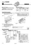
T Kit (Terminal block box kit) Manifold Specifications Series VQ5000 Porting specifications Rc 3/4 Rc 3/8 Rc 1/2 Rc 1/2 VV5Q Manifold Option 08 Stations 03 T K Cylinder port 03 04 B CM 1 Plug-in unit 1 Series 5 VQ5000 D U 5 Applicable terminal: 1.25-3s, 1.25Y-3, 1.25Y-3N, 1.25Y-3.5 Name plate: VVQ5000-N-T Dripproof plug assembly (for G 3/4): AXT100-B06A 0.7 to 1.2 Symbol Electrical entry 2 x G 3/4 6mm Terminal Block Connections How to Order Manifold IP65 compliant Enclosure IP65 compliant This type has a small terminal block inside a junction box. The provision of a G 3/4 electrical entry allows connection of conduit fittings. Maximum stations are 11. (12 stations as an option) 1 station is used for terminal block box mounting. 4(A), 2(B) port location Side Bottom Port size 1(P) , 5(R1) , 3(R2) 4(A) , 2(B) Applicable stations Max. 12 stations Step 1. How to remove terminal block cover Loosen the 4 mounting screws (M4) and open the terminal block cover. Step 2. The diagram on the right shows the terminal block wiring. All stations are provided with double wiring regardless of the valves which are mounted. Connect each wire to the power supply side, according to the markings provided inside the terminal block. Mounting screw (M4) Terminal block cover Gasket Step 3. How to attach the terminal block cover Securely tighten the screws with the torque shown in the table below, after confirming that the gasket is installed correctly. Proper tightening torque (N・m) M3 screw 02 2 stations 12 12 stations ・・・ ・・・ One station is used for mounting the terminal block box. The number of stations is the number of manifold valves plus one station for the terminal block box. For 12 stations, specify the wiring specifications by means of the manifold specification sheet. Note) Box mounting position D side mounting U side mounting Rc 3/8 Rc 1/2 Bottom ported Rc 1/2 Mixed Nil CD1 (2) CD2 (2) CU1 (2) CU2 (2) K (3) N SD (2) SU (2) W Option None Exhaust cleaner for Rc 1: D side exhaust Exhaust cleaner for Rc 1 1/2: D side exhaust Exhaust cleaner for Rc 1: U side exhaust Exhaust cleaner for Rc 1 1/2: U side exhaust Special wiring specification (Except double wiring), 12 stations Name plate Direct exhaust with silencer box: D side exhaust Direct exhaust with silencer box: U side exhaust IP65 enclosure When two or more symbols are specified, indicate them alphabetically. Example) -CD1K. Combination of [CD U ] and [SD U ] is not possible. Specify the wiring specifications on the manifold specification sheet. Note 1) Note 2) Note 3) [Option] CE-compliant Nil . Q CE-compliant 1120 Series VQ5000