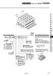
VQ 5 Type of actuation Series 1 2 3 4 5 6 Seal 0 1 Coil voltage Manual override Light/Surge voltage suppressor 5 VQ5000 1 0 0 5 1 2 3 4 5 6 Function How to Order Valves How to Order Manifold Assembly [Order example] U side D side Stations ・・・・・・・・・・・・ 3 2 1 2 position single 2 position double 3 position closed center 3 position exhaust center 3 position pressure center 3 position double check Metal seal Rubber seal Nil Y (1) R (2) Standard type (1 W) Low wattage type (0.5 W) External pilot 100 VAC (50/60 Hz) 200 VAC (50/60 Hz) 110 VAC (50/60 Hz) 220 VAC (50/60 Hz) 24 VDC 12 VDC Nil B Non-locking push type (Tool required) Locking type (Tool required) Nil E Yes Without light, with surge voltage suppressor Specify the part numbers for valves and options together beneath the manifold base part number. Individual terminal block kit VV5Q51-0503T1(-Q)・・ 1 set .VQ5100-5(-Q) ・・・ 2 sets .VQ5200-5(-Q) ・・・ 2 sets .VQ5300-5(-Q) ・・・・ 1 set .Manifold base part no. .Valve part no. (Stations 1 and 2) .Valve no. (Stations 3 and 4) .Valve part no. (Station 5) Enter in order starting from the first station on the D side. When entry of part numbers becomes complicated, indicate in the manifold specification sheet. Prefix the asterisk to the part nos. of the solenoid valve, etc. 1 2 3 ・・・・・・・・・・・・・・・・ Stations D side U side Note 1) Applicable to DC specification. Please select when you expect to energize the unit for extended periods of time. Refer to page 3 for details. Note 2) Refer to page 1145 for details on external pilot specifications. Note 3) When two or more symbols are specified, indicate them alphabetically. Base Mounted Plug-in Unit Series VQ5000 [Option] CE-compliant Nil . Q CE-compliant 1125 SY SJ SY SV SYJ SZ VF VP4 S0700 VQ VQ4 VQ5 VQC VQC4 VQZ SQ VFS VFR VQ7
