1-p1109-1152-vq5000_en 26 / 45
10秒後にBOOKのページに移動します
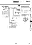
VQ 5 Type of actuation Series 1 2 3 4 5 6 Seal 0 1 Coil voltage Manual override 5 VQ5000 1 0 0 5 24 VDC Function Enclosure Nil W 5 How to Order Valves How to Order Manifold Assembly [Order example] 2 position single 2 position double 3 position closed center 3 position exhaust center 3 position pressure center 3 position double check Metal seal Rubber seal Dusttight Dusttight/Low jetproof type (IP65) Nil B Non-locking push type (Tool required) Locking type (Tool required) Nil Y (1) R (2) Standard type (1 W) Low wattage type (0.5 W) External pilot Note 1) Applicable to DC specification. Please select when you expect to energize the unit for extended periods of time. Refer to page 3 for details. Note 2) Refer to page 1145 for details on external pilot specifications. Note 3) When two or more symbols are specified, indicate them alphabetically. CE-compliant Nil . Q CE-compliant