1-p1453-1583-vfs1000_enü@ü@ü@128 / 132
10ĢbīŃé╔BOOKé╠āyü[āWé╔ł┌ō«éĄé▄éĘ
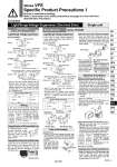
SOL. With indicator light Black Lead wire, red B side A side SOL. White With indicator light lead wire, brown SOL. With indicator light Black Red Note) There is no polarity (+, .). .(+) +(.) SOL. With indicator light Terminal no. 2 .(+) Terminal no. 1 +(.) .(+) +(.) B side A side SOL. Terminal no. 2 .(+) With indicator light Terminal no. 1 +(.) SOL. With indicator light Terminal no. 2 .(+) Terminal no. 1 +(.) .(+) +(.) SOL. With indicator light Terminal no. 2 (.) Terminal no. 1 (+) SOL. With indicator light Terminal no. 2 (.) Terminal no. 1 (+) B side A side SOL. Terminal no. 2 (.) With indicator light Terminal no. 1 (+) SOL. With indicator light Terminal no. 2 (.) Terminal no. 1 (+) .(+) +(.) B side A side SOL. Terminal no. 2 (.) With indicator light Terminal no. 1 (+) SOL. With indicator light Terminal no. 2 (.) Terminal no. 1 (+) (1) (2) Pilot valve assembly Pilot valve assembly Light/Surge Voltage Suppressor, Electrical Entry Single unit Series VFS1000/2000/3000 Body Ported Base Mounted Series VFS2000 Light/Surge Voltage Suppressor Caution Light/Surge Voltage Suppressor In the case of DIN terminal and terminal block (with indicator light/surge voltage suppressor), the interior wiring is shown below. Note) There is no polarity. To change direction of DIN terminal retaining screw, pull off outer cover, rotate connector board through 180üŗ. Replace cover and tighten screw. Loosen the set screw (M3.2 pcs.), take out pilot operator, turn solenoid valve 180üŗ degrees to change the direction of lead wire and manual override. (Possible on Series VFS1000 only.) Applicable terminal: 1.25- 3, 1.25-3S, 1.25Y-3N, 1.25Y-3S, but in the case of with DIN terminal block, is not a terminal structure. Surge voltage suppressor DC AC Manual position Wiring Changing Direction of DIN Terminal/Cable Entry Changing Direction of Electrical Entry and Manual Override With DIN terminal block With terminal block . Type G: Lead wire comes directly from the solenoid part. Connect it with the power source. Grommet with DC voltage surge voltage suppressor has polarity. Connect red lead wire to + (positive) side and black to . (negative) side. Note) There is no polarity (+, .). Note) There is no polarity (+, .). Varistor . In the case of surge voltage suppressor, surge voltage absorption device ZNR is attached to AC power. Plug-in type Non plug-in type . Type G: Use lead wire from solenoid to connect with power side. Grommet with DC voltage surge voltage suppressor has polarity. Connect red lead wire to + (positive) side and black to . (negative) side. Surge voltage suppressor DC AC How to Exchange Solenoid valve . Loosen 3 set screws (hexagonal socket head cap screw M3 x 31) and pull solenoid valve out vertically, otherwise it may cause damage to the solenoid valve. Never remove a valve at an angle. . When mounting solenoid valve onto the base, plug pin assembly (base side) into receptacle assembly (body-side) vertically. With light/surge voltage suppressor Receptacle assembly With light/surge voltage suppressor Red + Black . Diode Varistor Diode Exchange of pilot valve (Voltage exchange) . When changing rated voltage and electrical entry etc., pilot valve assembly can be changed. But in case of a plug-in type with light/surge voltage suppressor, pilot valve assembly cannot be changed for changing rated voltage. . Change of the electrical entry of DIN type connector cable Unscrew retaining screw, pull off outer cover, rotate connector board through 180üŗ. Replace cover and tighten screw. Applicable cable: O.D. o6 to o8. Single unit/Plug-in type sub-plate: T Conduit terminal (With terminal block) . If the junction cover (1) of the sub-plate is removed, you can see the plug-in type terminal block (2) (part no. NVF2000-27A-1) mounted inside the sub-plate. The following markings are on the terminal block board. Connect with corresponding power side. Description Terminal block marking Solenoid A side Solenoid B side Applicable terminal: 1.25- 3, 1.25-3S, 1.25Y-3N, 1.25Y-3S, but in the case of with DIN connector board, is not a terminal structure. Tightening torque for terminal: 0.6 NüEm Note) There is no polarity. Changing Direction of DIN Terminal/Cable Entry Electrical Connection With DIN terminal block With terminal block . There is no polarity. . When ground wiring and COM wiring are required, please specify separately. . Applicable terminal: 1.25-3, 1.25-3S, 1.25Y- 3N, 1.25Y-3S Single unit/Non plug-in type sub-plate: G, E, T, D . Type G: Use lead wire from solenoid to connect with power side. . Type E, T, D: In the case of a DIN terminal and terminal block (with light/surge voltage suppressor), the interior wiring is shown below. Connect with corresponding power side. Varistor Varistor Varistor Varistor Single Double Double Note) There is no polarity (+, .). Varistor Varistor Varistor Varistor Varistor Varistor Varistor Varistor A. A+ B+ B. AC and 100 VDC 24 VDC or less Single Red + Black . AC and 100 VDC Single Double 24 VDC or less Single Double . When mounting pilot valve assemblies and solenoid valve bodies, tighten equally with the tightening torque shown in the right to prevent gaskets from slipping. Pilot Valve Assembly SF4-«-« Holding screw M3 Proper tightening torque (NüEm) 0.45 to 0.6 Holding screw M3 Proper tightening torque (NüEm) 0.8 to 1.2 Solenoid Valve Body Series VFS Specific Product Precautions 1 Be sure to read before handling. Refer to front matter 53 for Safety Instructions and pages 3 to 8 for 3/4/5 Port Solenoid Valve Precautions. 1579 SY SJ SY SV SYJ SZ VF VP4 S0700 VQ VQ4 VQ5 VQC VQC4 VQZ SQ VFR VQ7 VFS A