1-p1453-1583-vfs1000_en@@@129 / 132
10bÐèBOOKäy[WèÖÛçÉñ
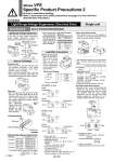
SOL.A With indicator light 3 1 2 SOL.B With indicator light SOL.A With indicator light 3 1 2 SOL.B With indicator light SOL.A With indicator light 3 1 2 SOL.A With indicator light 3 1 2 ~ ~ SOL. With indicator light .(+) +(.) SOL. With indicator light Ground VFS6000 Pilot cover Mounting screw Pilot valve assembly Base Mounted Series VFS3000/4000/5000/6000 Light/Surge Voltage Suppressor Substrate Part No. VFS4000 VFS3000 VFS5000 VFS6000 VFS3000-10A-ÞÙ#1 100V or more 24V or less 100V or more 24V or less 100V or more 24V or less VF4000-9A-ÞÙ#1 VF4000-9B-ÞÙ#1 AXT627-7A-ÞÙ#1 AXT627-7B-ÞÙ#1 VF4000-9A-ÞÙ#1 VF4000-9B-ÞÙ#1 -ÞÙ: Coil rated voltage Symbol: Refer to below. 1: 100 to 120 V 2: 200 to 220 V 5: 24 V 6: 12 V 7: 240 V Light/Surge Voltage Suppressor, Electrical Entry Single unit Light/Surge Voltage Suppressor How to Exchange Lead Wire Connection In the case of surge voltage suppressor, surge voltage absorption element is attached to terminal block on body area. 100 VAC/DC or more 24 VDC or less Note) There is no polarity. Light/Surge voltage absorption element Caution VFS3000/4000/5000 Solenoid valve . Loosen set screw and take solenoid valve out vertically, otherwise it may cause damage to the solenoid valve. Never remove a valve at an angle. . When mounting solenoid valve onto the base, plug pin assembly (base side) into receptacle assembly (body side) vertically. Pilot valve . When changing the rated voltage, electrical entry, etc., pilot valve assembly can be exchanged easily since this is plug-in type. Then, when changing the rated voltage with indicator light/surge voltage suppressor, change of indicator light/surge voltage suppressor substrate is also needed. So, order together with pilot valve assembly. Plug-in type (With terminal) . If the junction cover (1) of the sub-plate is removed, you can see the plug-in type terminal block (2) mounted inside the sub-plate. DIN terminal block type . Male pin terminal of DIN terminal block board of solenoid valve and wires as shown below. Connect to corresponding terminal block on the connector. . There is no polarity. DIN terminal (Wiring) 1 2 3 A side B side COM Ground . Heavy-duty cord Applicable cable O. D.: o8 to o10 . Applicable terminal Applicable terminal on block board: 3 (kinds) 1.25Y-3L, 1.25-3.5S, 1.25-4M . Connector/Clamping torque Set screw 0.6 NEm Terminal screw 0.6 NEm . Incorrect common (DIN terminal no. 3) causes damage on power side circuit. Terminal block marking Solenoid A side Solenoid B side A B + . + . . Applicable terminal: VFS3000: 1.25-3, 1.25-3S, 1.25Y-3N, 1.25Y-3S VFS4000: 1.25-3.5M, 1.25Y-3L, 1.25Y-3M VFS5000: 1.25-4, 1.25-4M VFS6000: 1.25-3.5M, 1.25Y-3L, 1.25-3M . There is no polarity. . Tightening torque for terminal: 0.6 NEm Non plug-in type (With terminal) . Remove cover (1), over terminal block (2) attached to the inside of body. Connect with corresponding power side. For a type with indicator light and surge voltage suppressor, pull out the light and surge voltage suppressor substrate (3) in a straight direction and then connect them. . Applicable terminal: VFS3000: 1.25-3, 1.25-3S, 1.25Y-3N, 1.25Y-3S VFS4000/5000/6000: 1.25-3.5M, 1.25Y-3L, 1.25Y-3M . There is no polarity. . Tightening torque for terminal: 0.6 NEm . The following markings are on the terminal block. Connect with corresponding power side. (1) (1) (3) (2) (2) A side B side B side A side A side B side Varistor Varistor Varistor Varistor Varistor Varistor Varistor Varistor 100 VAC/DC or more Single Single Double Double 24 VDC or less . When mounting pilot valve assemblies and solenoid valve bodies, tighten equally with the tightening torque shown in the right to prevent gaskets from slipping. Pilot Valve Assembly SF4-ÞÛ-ÞÛ Holding screw M3 Proper tightening torque (NEm) 0.45 to 0.6 Holding screw M3 M4 M5 Proper tightening torque (NEm) 0.8 to 1.2 1.4 to 2.5 2.8 to 5 Solenoid Valve Body 1580 Series VFS Specific Product Precautions 2 Be sure to read before handling. Refer to front matter 53 for Safety Instructions and pages 3 to 8 for 3/4/5 Port Solenoid Valve Precautions. A