1-p1453-1583-vfs1000_en 130 / 132
10秒後にBOOKのページに移動します
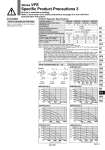
Symbol P port regulation A port regulation B port regulation B A P R1 R2 A B P R1 R2 R1 R2 A B P Refer to front matters 42 to 45 for How to Calculate the Flow Rate. How to Calculate the Flow Rate Caution Interface Regulator Specifications Interface regulator (3) (4) Applicable solenoid valve series Regulating port Proof pressure Maximum operating pressure ARBF2000 ARBF3050 ARBF4050 ARBF5050 VFS2000 VFS3000 VFS4000 VFS5000 P M5 x 0.8 0.16 5.5 5.1 P → A P → B 12 11 A → EA B → EB 0.46 18.5 22 40 36 0.72 31 31 55 45 0.83 38 40 11 12 26 24 32 31 21 18.5 35 31 44 38 90 77 A B A B A Rc 1/8 P P B P 1.0 MPa 1.5 MPa Set pressure range (1) 0.05 to 0.83 MPa 0.1 to 0.83 MPa Ambient and fluid temperature .5 to 60°C (No freezing) Port size for connection of pressure gauge Weight (kg) Effective area at supply side (mm2) (2) S at P1 = 0.7 MPa, P2 = 0.5 MPa Effective area at exhaust side (mm2) (2) S at P2 = 0.5 MPa Note 1) Set within the operating pressure range of solenoid valve. Note 2) Synthesized effective area with solenoid valve 2 position single type. Note 3) . Operate an interface regulator only by applying pressure from the “P” port of the base, except when using it as a reverse pressure valve. . To combine a pressure center valve and the A and B port pressure reduction of an interface regulator, use the ARBF3000, 4000, or 5000 model. . To combine a reverse pressure valve and an interface regulator, use the ARBF3000, 4000, or 5000 model. Furthermore, the P port pressure reduction cannot be used for the reverse pressure valve. . When combining a double check valve and an interface regulator, use a manifold or sub-plate as a basis, and stack them in the following order; the perfect spacer → the interface regulator → the valve. . When a closed center valve is combined with the interface regulator's A, B port regulation, note that it cannot be used for intermediate stops of a cylinder because there is leakage from relief port on the regulator. Note 4) Note that the pressure gauge (G27) for the ARBF2000-00-P- cannot be used for the oil lubricating air. ARBF3050-00-P ARBF2000-00-P ARBF4050-00-P ARBF5050-00-P ARBF3050-00-A ARBF4050-00-A ARBF5050-00-A Flow Characteristics (P → A) (Representative value conditions: Inlet pressure 0.7 MPa. when 2 position solenoid valve is mounted.) Flow rate (L/min (ANR)) Outlet pressure (MPa) Flow rate (L/min (ANR)) Outlet pressure (MPa) Flow rate (L/min (ANR)) Outlet pressure (MPa) Flow rate (L/min (ANR)) Outlet pressure (MPa) Flow rate (L/min (ANR)) Outlet pressure (MPa) Flow rate (L/min (ANR)) Outlet pressure (MPa) Flow rate (L/min (ANR)) Outlet pressure (MPa) 1581 Series VFS Specific Product Precautions 3 Be sure to read before handling. Refer to front matter 53 for Safety Instructions and pages 3 to 8 for 3/4/5 Port Solenoid Valve Precautions. SY SJ SY SV SYJ SZ VF VP4 S0700 VQ VQ4 VQ5 VQC VQC4 VQZ SQ VFR VQ7 VFS A