1-p1453-1583-vfs1000_en 132 / 132
10秒後にBOOKのページに移動します
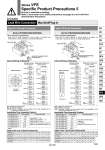
Multi-connector Standard wiring Wiring with control unit D-sub connector Standard wiring Wiring with control unit Pressure switch 24 23 COM 22 SOL.B SOL.A 7 station 21 20 COM 19 SOL.B SOL.A 6 station 18 17 COM 16 SOL.B SOL.A 5 station 15 14 COM 13 SOL.B SOL.A 4 station 12 11 COM 10 SOL.B SOL.A 3 station 9 8 COM 7 SOL.B SOL.A 5 4 Connector terminal no. 2 1 Air release valve 24 23 COM 22 SOL.B SOL.A 7 station 21 20 COM 19 SOL.B SOL.A 6 station 18 17 COM 16 SOL.B SOL.A 5 station 15 14 COM 13 SOL.B SOL.A 4 station 12 11 COM 10 SOL.B SOL.A 3 station 9 8 COM 7 SOL.B SOL.A 2 station 6 5 COM 4 SOL.B SOL.A 1 station Connector terminal no. 3 2 COM 1 SOL.B SOL.A 12 24 COM 25 SOL.B SOL.A 7 station 23 10 COM 11 SOL.B SOL.A 6 station 9 21 COM 22 SOL.B SOL.A 5 station 20 7 COM 8 SOL.B SOL.A 4 station 6 18 COM 19 SOL.B SOL.A 3 station 17 4 COM 5 SOL.B SOL.A Connector terminal no. 12 24 COM 25 SOL.B SOL.A 7 station 23 10 COM 11 SOL.B SOL.A 6 station 9 21 COM 22 SOL.B SOL.A 5 station 20 7 COM 8 SOL.B SOL.A 4 station 6 18 COM 19 SOL.B SOL.A 3 station 17 4 COM 5 SOL.B SOL.A 2 station 3 15 COM 16 SOL.B SOL.A 1 station Connector terminal no. 14 1 COM 2 SOL.B SOL.A 15 16 1 2 Caution Type 01F D-sub Connector Series VFS2000/3000/4000/5000 Series VFS2000/3000/4000/5000 Lead Wire Connection Manifold/Plug-in Type 01C Circular Connector Note 1) Maximum stations are 8. Note 2) There is no polarity. Note 3) Indication of stations are one station from D side regardless of the connector mounting side, D or U. . Wire connection specifications Lead wire for both solenoid A and B sides in manifold are connected to connector terminal as COM specifications. . Wire connection specifications Lead wire for both solenoid A and B sides in manifold are connected to connector terminal as COM specifications. Internal Wiring of Manifold Applicable Plug Assembly (Option) VVFS2000-30A-1 VVFS2000-30A-2 Assembly part no. Cable length 1.5 m 3 m VVFS2000-30A-3 5 m VVFS2000-30A-4 . 7 m VVFS2000-30A-5 . 10 m VVFS2000-30A-6 . 15 m VVFS2000-30A-7 . 20 m Component parts Plug 206837-1 1 pc. Cable clamp 206138-1 1 pc. Socket 66101-2 24 pcs. Cable VCTF 24 cores x 0.75 mm2 made by Tyco Electronics AMP K.K. . Option Cable Color List of Each Terminal No. Terminal no. 1 Orange Orange . 2 Yes Yes Yes Yes Yes Yes 3 Black Black . 4 5 . 6 Green Green Red Red Blue Blue Yellow Yellow 7 . 8 9 . 10 11 . 12 Lead wire color Dot marking Terminal no. Lead wire color Dot marking Cable Color List of Each Terminal No. Terminal no. 1 Black Brown . . 2 White Black Red Red 3 Red Orange . . 4 5 . . 6 Yellow Pink Blue Purple Gray White White Yellow 7 . 8 9 Black 10 11 12 Lead wire color Note 1) Maximum stations are 8. Note 2) There is no polarity. Note 3) Indication of stations are one station from D side regardless of the connector mounting side, D or U. Internal Wiring of Manifold Applicable Plug Assembly (Option) AXT100-DS25-015 AXT100-DS25-030 Assembly part no. Cable length 1.5 m 3 m AXT100-DS25-050 5 m AXT100-DS25-080 8 m AXT100-DS25-100 10 m AXT100-DS25-150 15 m AXT100-DS25-200 30 m Component parts AXT100-DS25-300 20 m Dot marking Terminal no. Lead wire color Dot marking Black Black White Black White White Red White Yellow Pink Blue Purple Gray Orange Red Brown Pink 14 15 16 17 . 18 19 . . 20 21 22 Red Gray Black White 23 24 25 Fig. (1) U side D side Fig. (2) U side D side Plug: MIL standard D type connector 25 terminals Cable: 25 cores wire x 0.3 mm2 Applicable plug assembly (Option) (1) (2) (3) (n) (1) (2) (3) (n) Applicable plug assembly (Option) Connector terminal no. 1 station 2 station Control unit Max. 8 stations Max. 8 stations Connector terminal no. Air release valve 1 station 2 station Pressure switch Control unit Max. 8 stations Max. 8 stations 23 Yes Yes Yes Yes Yes Brown Brown White White Pink Pink Gray Gray Sky blue Sky blue Light green Light green 13 . 14 15 . 16 17 . 18 19 . 20 21 . 22 24 . Yes Stations Stations Red Orange 13 1583 Series VFS Specific Product Precautions 5 Be sure to read before handling. Refer to front matter 53 for Safety Instructions and pages 3 to 8 for 3/4/5 Port Solenoid Valve Precautions. SY SJ SY SV SYJ SZ VF VP4 S0700 VQ VQ4 VQ5 VQC VQC4 VQZ SQ VFR VQ7 VFS