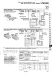
VV5FS2 01F 1 VV5FS2 10 D 06 10 2 02 1 01 Base model Plug-in type VV5FS2-01尰 Non plug-in type VV5FS2-10 Wiring . With attachment plug lead wire . With terminal block . With multi-connector . With D-sub connector . Grommet . Grommet terminal . Conduit terminal . DIN terminal A, B port P, EA, EB Port size Rc A, B Stations . With multi-connector, with D-sub connector: 8 stations at the maximum. Manifold Specifications Flow Characteristics at the Number of Manifold Stations (Operated individually) C [dm3/(s・bar)] b Cv Passage/Stations Station 1 Station 5 Station 10 b C [dm3/(s・bar)] 2.4 0.14 0.50 2.5 0.18 0.60 2.4 0.14 0.50 2.5 0.18 0.60 2.4 0.14 0.50 2.5 0.18 0.60 Cv Model VV5FS2 Please indicate manifold base type, corresponding valve, and option parts. . Plug-in type with terminal block (6 stations, one-piece style junction cover) (Manifold base) VV5FS2-01T1-061-02・・・・ 1 (2 position single) VFS2100-5FZ・・・・・・・・・・・・ 3 (2 position double) VFS2200-5FZ・・・・・・・・・・・ 2 (Blanking plate) VVFS2000-10A・・・・・・・・・・・・・ 1 . Non plug-in type (6 stations) (Manifold base) VV5FS2-10-061-01・・・・・・・・ 1 (2 position single) VFS2110-5D・・・・・・・・・・・・・ 3 (3 position exhaust center) VFS2410-5D・・・・・ 1 (Individual EXH spacer) VVFS2000-R-01-2・・・ 1 How to Order Manifold Assembly Porting specifications Side/Bottom 1 4 1 8 1 4 2 to 15. stations Applicable valve model VFS2尰00-尰F VFS2尰10-尰G VFS2尰10-尰E VFS2尰10-尰T VFS2尰10-尰D , 4/2 5/3 (A/B R1/R2) 1 4/2 (P A/B) . Port size Rc 1 4 Non Plug-in Type: Grommet, Grommet Terminal, Conduit Terminal, DIN Terminal . Wiring for every valve Note) The individual specification of the P port at the composition symbol 3 to 8 or the EA, EB, ports should be taken as individual port using a block plate. Therefore, if an individual port is using a single SUP spacer of option or a single EXH spacer, the composition symbol mark is “1”. . Wide range of interchangeability (D-sub connector (25P) conforming to MIL standard) . Quick wiring permits easier installation. Plug assembly Refer to page 1583. D-sub connector U side D side Plug-in Type: With D-sub Connector (Wiring specifications: Refer to page 1583.) Non plug-in type Series VFS2000 Manifold [Option] Plug-in type With D-sub connector D side mounting U side mounting D U Connector mounting direction . Max. 8 stations 1 station 8 stations 01 08 Stations CE-compliant Nil Q . CE-compliant Rc NPT NPTF G Nil N. T. F. Thread type . Semi-standard Port size Symbol P, EA, EB 01 02 M Rc 1 4 . For bottom ported, Rc 1/8 is only available. A, B Rc Rc Mixed 1 4 1 8 Symbol (Passage) Symbol Passage Porting P EA, EB specifications A, B 1 2. 3. 4. 5. 6. 7. 8. Side Bottom Side Bottom Side Bottom Side Bottom Common Individual Common Individual Common Common Individual Individual . Semi-standard . The external pilot type is not available. Series VFS2000 Manifold Nil R Internal pilot External pilot Pilot type 1 station 16 stations 01 16 Stations CE-compliant Nil Q . CE-compliant Rc NPT NPTF G Nil N. T. F. Thread type . Semi-standard Port size Symbol P, EA, EB 01 02 M Rc 1 4 . For bottom ported, Rc 1/8 is only available. A, B Rc Rc Mixed 1 4 1 8 Symbol (Passage) Symbol Passage Porting P EA,EB specifications A, B 1 2. 3. 4. 5. 6. 7. 8. Side Bottom Side Bottom Side Bottom Side Bottom Common Individual Common Individual Common Common Individual Individual Yes No Yes No External pilot . Semi-standard 1493 Series VFS2000 5 Port Pilot Operated Solenoid Valve Metal Seal, Plug-in/Non Plug-in SY SJ SY SV SYJ SZ VF VP4 S0700 VQ VQ4 VQ5 VQC VQC4 VQZ SQ VFR VQ7 VFS