1-p1453-1583-vfs1000_en 7 / 132
10秒後にBOOKのページに移動します
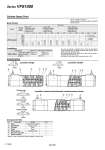
(A)4 2(B) 3 (R2) 1 (P) 5 (R1) 3 (R2) 5 (R1) 1 (P) (A)4 2(B) (A)4 2(B) 3 (R2) 1 (P) 5 (R1) (A)4 2(B) 3 (R2) 1 (P) 5 (R1) 5 (R1) 3 (R2) 1 (P) (A)4 2(B) VFS1120-01 800 700 600 500 400 300 200 100 0 o6 o10 o16 o20 o25 o32 o40 o40 o50 o63 o80 o100 Body Ported Construction Body ported Series CJ2 Series CM2 Series MB, CA2 VFS1120-01 Conditions 2 3 1 4 . . . 5 6 . 7 . . . . Component Parts Cylinder Speed Chart 2 position single 2 position double 3 position closed center/exhaust center/pressure center Closed center Exhaust center Pressure center Return spring Stainless steel Pilot valve assembly Detent assembly . Refer to “How to Order Pilot Valve Assembly” on page 1457. No. Description Stainless steel Resin Material Aluminum die-casted Note Spool/Sleeve Body End plate Piston Resin . Series Average speed (mm/s) Bore size Series CJ2 Pressure 0.5 MPa Load factor 50% Stroke 60 mm Series CM2 Pressure 0.5 MPa Load factor 50% Stroke 300 mm Series MB, CA2 Pressure 0.5 MPa Load factor 50% Stroke 500 mm Perpendicular, upward actuation Horizontal actuation Use as a guide for selection. Please confirm the actual conditions with SMC Sizing Program. AN101-01 T0604 x 1 m AS3002F-06 T0806 x 1 m AS3002F-08 Tube bore x Length Speed controller Silencer . It is when the cylinder is extending that is meter-out controlled by speed controller which is directly connected with cylinder, and its needle valve with being fully open. . The average velocity of the cylinder is the value that the stroke is divided by the total stroke time. . Load factor: ((Load mass x 9.8)/Theoretical force) x 100% 1458 Series VFS1000 A