1-p1453-1583-vfs1000_en 83 / 132
10秒後にBOOKのページに移動します
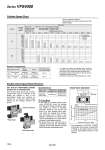
Cylinder Speed Chart Double Check Spacer/Specifications Plug-in type Check Valve Operation Non plug-in type Double check spacer System A 800 700 600 500 400 300 200 100 0 B 800 900 900 1000 1000 700 600 500 400 300 200 100 0 Bore size o50 o63 o80 o100 o125 o140 o160 o180 o200 o250 o300 Can hold an intermediate cylinder position for an extended time If the double check spacer with a built-in double check valve is combined, it will enable the cylinder to stop in the intermediate stroke and maintain its position for a long time without being affected by the leakage between the spools. Specifications . In the case of 3 position double check valve (VFS46尰0), check the leakage from piping and fittings in between valve and cylinder by means of synthetic detergent solutions, and ensure that there is no such leakage found there. Also check the leakage from cylinder seal and piston seal. If there is any leakage, sometimes the cylinder, when valve is de-energized, can move without stopping at intermediate position. . Be aware that if the exhaust side is restricted excessively, the intermediate stopping accuracy will decrease and will lead to improper intermediate stops. . The combination of VFS410 10, VFS420 10 and Double check spacer for prevention of falling at the stroke end but cannot hold the intermediate position of the cylinder. System Solenoid valve Speed Silencer controller SGP (Steel pipe) Port size x Length 10A x 1 Series VFS4000 Rc Series VFS4000 Rc A B AN30-03 (S = 60 mm2) AN40-04 (S = 90 mm2) AS420-03 (S = 73 mm2) AS420-04 (S = 97 mm2) 15A x 1 3 8 1 2 Double check spacer part no. Applicable valve model Plug-in type VVFS4000-22A-1 VFS4400-尰F Non plug-in type VVFS4000-22A-2 VFS4410-尰D VFS4410-尰E Average speed (mm/s) Series CA2 Pressure 0.5 MPa Load factor 50% Stroke 500 mm Series CS1/CS2 Pressure 0.5 MPa Load factor 50% Cylinder stroke 1000 mm Perpendicular, upward actuation Horizontal actuation Use as a guide for selection. Please confirm the actual conditions with SMC Sizing Program. System Components . It is when the cylinder is extending that is meter-out controlled by speed controller which is directly connected with cylinder, and its needle valve with being fully open. . The average velocity of the cylinder is what the stroke is divided by the total stroke time. . Load factor: ((Load mass x 9.8)/Theoretical force) x 100% Check valve Piston SUP side pressure (P1) Operating range Cylinder side pressure P2 (MPa) Cylinder side pressure (P2) SUP side pressure P1 (MPa) Caution Note) The CA1 series has been changed to the CA2 series. 1534 Series VFS4000