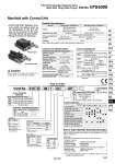
[Option] Manifold Specifications Plug-in type Non plug-in type Caution When using an air filter with auto-drain or manual drain, mount the filter vertically. How to Order Note 1) With multi-connector, or with D-sub connector: 8 stations max. VV5FS4 01C D 08 1 03 AP Series VFS4000 Manifold Air release valve coil rating Nil 1 01T 5 01C 01F 10 Base type/Electrical entry 02 10. Stations Manifold with Control Unit Control Unit Specifications Control Unit/Option Air filter (With auto-drain/With manual drain) Filtration degree Regulator Set pressure (Outlet pressure) Pressure switch (1) Set pressure range: OFF Differential Contact Max. switch capacity Max. operating current Air release valve (Single only) Operating pressure range 5 μm 0.05 to 0.85 MPa 0.1 to 0.6 MPa 0.1 to 1.0 MPa 0.08 MPa or less 1a Indicator light LED (RED) 2 VA AC, 2 W DC 24 VAC/DC or less: 50 mA 48 VAC/DC: 40 mA 100 VAC/DC: 20 mA Air release valve spacer Pressure switch Blanking plate Filter element VVFS4000-24A-1R (D side mounting) VVFS4000-24A-2R (D side mounting) IS1000P-2-1 Filter regulator Pressure switch Release valve MP2-3 MP3-2 VVFS4000-24A-10 11104-5B Note 1) Voltage: 24 VDC to 100 VAC Inner voltage drop: 4 V Note 2) Combination of a valve VFS41 (single) and a release valve spacer can be used as an air release valve. Note 3) The non plug-in type cannot be mounted afterwards. Air filter with auto-drain Control equipment Symbol Air filter with manual drain Regulator Air release valve Pressure switch Blanking plate (Air release valve) Blanking plate (Filter, Regulator) Blanking plate (Pressure switch) Number of manifold blocks required for mounting (stations) A AP M MP F G C E Control unit type None (F, G type only) 100 VAC, 50/60 Hz 24 VDC Q CE-compliant Nil . CE-compliant Plug-in type with terminal block Plug-in type with multi-connector Plug-in type with D-sub connector Non plug-in type Symbol Applicable base D Nil U 01C, 01F 01T, 10 With connector D side mounting None U side mounting Connector mounting direction Port size Thread type . Base type 01T, 10: 2 to 10 stations Base type 01C, 01F: 2 to 8 stations Symbol P, R1, R2 A, B Rc Rc Rc Mixed 1 1 2 2 3 8 Rc NPT NPTF G Nil N. T. F. (Manifold base) (2 position single) (2 position double) . Non plug-in type: In order to mount control unit, it requires 2 stations. (Manifold base) (2 position single) 1 4 2 1 4 VV5FS4-01T-081-03-AP5 VFS4100-5FZ VFS4200-5FZ VV5FS4-10-061-03-A VFS4110-5D 2 stations 10 stations . For bottom ported, Rc 3 8 is only available. . Control unit (Filter, Regulator, Pressure switch, Air release valve) are all standardized to the one unit, and can be mounted on the manifold base without any attachments. . Piping processes are eliminated. ・・・ ・・・ Symbol Symbol 1 Side 2 Bottom. Passage P R1, R2 Common Common . Semi-standard . Semi-standard Porting specifications (A, B) 2 2 2 2 2 2 2 1 Nil Manifold Wiring Applicable valve model Porting specifications Rc (PT) Stations Plug-in type: VV5FS4-01 Non plug-in type: VV5FS4-10 With terminal block With multi-connector With D-sub connector DIN terminal Grommet terminal VFS400-F VFS410-D, VFS410-E Common SUP, Common EXH Side: 3/8, 1/2, Bottom: 3/8 Side: 1/2 2 to 10 (1) 2(B), 4(A) port 1(P), 3(R2), 5(R1) port How to Order Manifold Assembly [Example] Add the valve and option part numbers in order starting from the first station on the D side. . . . The asterisk denotes the symbol for assembly. Prefix it to the part numbers of the solenoid valve. . Plug-in type with terminal block: In order to mount control unit, it requires 2 stations. (2) (3) 03 04 M For other rated voltages, please consult with SMC. 1545 Series VFS4000 5 Port Pilot Operated Solenoid Valve Metal Seal, Plug-in/Non Plug-in SY SJ SY SV SYJ SZ VF VP4 S0700 VQ VQ4 VQ5 VQC VQC4 VQZ SQ VFR VQ7 VFS