1-p1453-1583-vfs1000_en 97 / 132
10秒後にBOOKのページに移動します
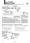
Refer to page 2055 and the Operation Manual for the details of EX123/124 Integrated-type (For Output) Serial Transmission System. Please download the Operation Manual via our website, http://www.smcworld.com VV5FS4 01S X199 Nil Rc NPT NPTF G Thread type NTF Plug-in type Serial transmission kit Stations 02 10 2 stations 10 stations Note 1) Max. 10 stations. Add 1 station for serial unit mounting. Note 2) Max. 10 Stations: For single and double mixed wiring. (No. of valves: 9) Max. 9 stations: For standard double wiring (No. of valves: 8) Combination symbol Symbol Port specification P R1, R2 Side Bottom Piping specification A, B Common Common 12 . . Semi-standard Port size Symbol 03 04 M P, R1, R2 A, B Rc 1/2 . For bottom ported: Rc 1/8 only Rc 3/8 Rc 1/2 Mixed SI unit mounting position DU D side mounting U side mounting Applicable models For U side mouning For D side mouning . EX123U-SUW1 EX123U-SUH1 EX123U-SSL1 EX123U-SSL2 EX124U-SDN1 EX124U-SCS1 EX124U-SCS2 EX124U-SMJ1 . EX123D-SUW1 EX123D-SUH1 EX123D-SSL1 EX123D-SSL2 EX124D-SDN1 EX124D-SCS1 EX124D-SCS2 EX124D-SMJ1 Description SI unit part no. Without SI unit NKE Corporation: Fieldbus System (16 outputs) NKE Corporation: Fieldbus H System (16 outputs) Panasonic Industrial Devices SUNX Co., Ltd.: S-LINK System (16 outputs) Panasonic Industrial Devices SUNX Co., Ltd.: S-LINK System (8 outputs) DevieNet (2 power supply systems) OMRON Corporation: CompoBus/S (16 outputs) (2 power supply systems) OMRON Corporation: CompoBus/S (8 outputs) (2 power supply systems) CC-Link (2 power supply systems) Symbol 0 F1 H J1 J2 Q R1 R2 V Correspondence of SI unit output numbers and solenoid valve coils