es11-103-sy 206 / 263
10秒後にBOOKのページに移動します
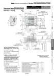
1 P 3/5 E 1 P 3/5 E 2 B 4 A 2 B 4 A 2 B 4 A LOCK FREE B A 12 B 14 A 14 A 12 B B A 4 A 2 B 4 A 2 B B A 14 A 12 B B A 14 A 12 B B A 14 A 4 x M5 mounting hole (Fitting for the type with P and E ports on both sides) Light/surge voltage suppressor DIN rail holding screw (For DIN rail mounting) DIN rail 1.5 5.5 35 8 10.9 97.5 (61.7) (8.3) (5.9) 81.2 113.4 12.4 33.4 (7.5) 18 (20.5) 61.7 5.5 35.9 21.9 8.7 4.7 (L5) 5.3 L1 L2 (L4) (DIN rail mounting hole pitch: 12.5) (L3) P = 12.5 78.9 (Slide locking manual override) 31.5 (SY3000) 73.2 ( P i t c h o f ) SY3000 P = 16 Note) Refer to pages 181 and 182 for dimensions of external pilot, built-in silencer and elbow fittings. D side U side ( ) 4(A) port side : Blue (For rubber seal) : Gray (For metal seal) 2(B) port side : Yellow Push-turn locking slotted type: Press, then rotate it. Manual override One-touch fitting [4(A), 2(B) port] Applicable tube O.D.: o2 : o3.2, o1/8" : o4, o5/32" : o6, o1/4" One-touch fitting [4(A), 2(B) port] Applicable tube O.D.: o4, o5/32" : o6, o1/4" : o8, o5/16" One-touch fitting [1(P), 3/5(E) port] Applicable tube O.D.: o10, o3/8" Compatible with mixed mounting type: o8, o5/16" SY3000 (Station 1)---------(Station n) One-touch fitting [4(A), 2(B)port] Applicable tube O.D.: o8, o5/16" 14.1 (SY5000 and SY3000: o8, o5/16") 29.1 (SY5000 and SY3000: o8, o5/16") ( P i t c h o f ) SY5000 P = 16 ( P it c h o f S Y 3 0 0 0 : o 8 , ) o5/16" 11.1 (SY3000) (11.8) (For DIN rail mounting) Dimensions: Series SY3000/5000 Plug-in Connector Connecting Base Type 10/Side Ported Mixed Mounting Type L1 = 12.5 x n1 + 16 x n2 + 76.4 L2 = 12.5 x n1 + 16 x n2 + 48 M = (L1 + 6.1)/12.5 + 1 Decimal fractions are truncated. L3 = 12.5 x M + 23 L4 = L3 . 10.5 L5 = (L3 . L1 + 6.1)/2 Calculation formula for dimensions with D-sub connector