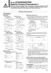
[SOL.b] (+) [SOL.a] (+) COM (.) [SOL.b] (.) [SOL.a] (.) COM (+) [SOL.a] (+) COM (.) [SOL.a] (.) COM (+) Polarity protection diode LED (.) (+) i2 i1 (.) (+) Coil Coil Coil Coil LED (Orange) Polarity protection diode Coil Coil Polarity protection diode Polarity protection diode LED (Green) [SOL.b] (+) [SOL.a] (+) COM (.) LED (Orange) Polarity protection diode [SOL.a] (+) COM (.) Coil Varistor Coil Varistor Coil Coil Coil Coil LED (Orange) Varistor LED Coil Varistor LED Coil Polarity protection diode Coil Coil Varistor Coil Polarity protection diode Polarity protection diode LED (Green) [SOL.b] (.) [SOL.a] (.) COM (+) LED Polarity protection diode [SOL.a] (.) COM (+) Varistor SOL.b (.,+) COM SOL.a (.,+) (+,.) LED Coil SOL.b (.,+) COM SOL.a (.,+) (+,.) SOL.a (.,+) COM (+,.) SOL.a (.,+) COM (+,.) Coil Coil Diode Diode Timer circuit PWM circuit i1: Starting current, i2: Holding current Polarity protection diode Not available for the 12 VDC specification. Electric circuit diagram (With power saving circuit) In the case of single solenoid Single solenoid Single solenoid Double solenoid Double solenoid Positive common Single solenoid Negative common Single solenoid Light/surge voltage suppressor (尰Z) Light/surge voltage suppressor (尰NZ) Surge voltage suppressor (尰S) Surge voltage suppressor (尰NS) Positive common Double solenoid, 3-position, 4-position Negative common Double solenoid, 3-position, 4-position Light/surge voltage suppressor (尰Z) Light/surge voltage suppressor (尰NZ) Surge voltage suppressor (尰S) Surge voltage suppressor (尰NS) Light/Surge Voltage Suppressor Caution 傖 With power saving circuit Power consumption is decreased by approx. 1/3 by reducing the wattage required to hold the valve in an energized state. (Effective energizing time is over 67 ms at 24 VDC.) 傖 Polar type With surge voltage suppressor (尰R) With light/surge voltage suppressor (尰U) Applied voltage Standard With power saving circuit 67 ms (40 ms) 24 V 0 V 0.35 (0.9) W 0.1 (0.4) W 0 W The values in ( ) are for the high pressure and quick response types. The above circuit reduces the power consumption for holding in order to save energy. Refer to the electrical power waveform as shown below. . The 12 VDC specification with power saving circuit (standard specification) does not have the polarity protection diode. Do not make a mistake with the polarity. . Since the voltage will drop by approx. 0.5 V due to the transistor, pay attention to the allowable voltage fluctuation. (For details, refer to the solenoid specifications of each type of valve.) Residual voltage of the surge voltage suppressor Note) If a varistor or diode surge voltage suppressor is used, there is some residual voltage to the protection element and rated voltage. Therefore, refer to the below table and pay attention to the surge voltage protection on the controller side. Also, since the response time does change, refer to the valve specifications on page 4. Surge voltage suppressor S, Z R, U DC 24 V Approx. 1 V Approx. 47 V Approx. 32 V 12 V Residual Voltage Series SY3000/5000/7000 Specific Product Precautions 3 傖 Non-polar type Note) Be careful of the energizing time, as quick response and high pressure types will become operational when the energizing time is over 40 ms. Be sure to read before handling. Refer to back cover for Safety Instructions. For 3/4/5 Port Solenoid Valve Precautions, refer to “Handling Precautions for SMC Products” and the Operation Manual on SMC website, http://www.smcworld.com 244