2-p1151-1165-cc_en 14 / 16
10秒後にBOOKのページに移動します
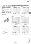
If intricate speed control is unnecessary and the changes in speed due to load fluctuations can be tolerated, the pneumatic speed controller can be used as a control valve. The minimum controllable flow volume of the speed controller is 3 dm3/min. The speed controller and the converter must have individual pipe connections. They cannot be integrated into a unit. Circuit diagram Speed controller Refer to Best Pneumatics No. 6 for the details of speed controllers. Cylinder driving speed (mm/s) Bore size (mm) Piping bore Piping bore Piping bore Piping bore Piping bore Piping bore Cylinder driving speed (mm/s) Bore size (mm) Cylinder driving speed (mm/s) Bore size (mm) Cylinder driving speed (mm/s) Bore size (mm) Cylinder driving speed (mm/s) Bore size (mm) Cylinder driving speed (mm/s) Bore size (mm) AS420-02/03/04 AS600-10 AS3000-02/03 AS500-06 AS2000-01/02 Maximum Driving Speed of Cylinders (Speed controller) Conditions: Operating pressure . 0.5 MPa, Operating oil . Turbine oil Class 1 (ISO VG32), Piping length . 1 m AS4000-02/03/04 Load ratio Load ratio Load ratio Load ratio Load ratio Load ratio Air-hydro Unit Series CC No load No load No load No load No load No load 1163 CC D- -X Technical data