2-p1151-1165-cc_en 5 / 16
10秒後にBOOKのページに移動します
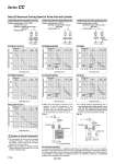
Cylinder driving speed (mm/s) Bore size (mm) Cylinder driving speed (mm/s) Bore size (mm) Cylinder driving speed (mm/s) Bore size (mm) Cylinder driving speed (mm/s) Bore size (mm) Cylinder driving speed (mm/s) Bore size (mm) Cylinder driving speed (mm/s) Bore size (mm) Cylinder driving speed (mm/s) Bore size (mm) Flow control valve Flow control valve Throttle valve Throttle valve Stop valve Piping bore Piping bore Piping bore Piping bore Load ratio No load Load ratio Piping bore Piping bore Load ratio Load ratio No load No load No load Converter Air-hydro unit Control direction Converter Converter Valve unit Valve unit Cylinder driving speed when operating flow control valve Condition: Operating press.: 0.3 to 0.7 MPa Load ratio: 50% or less Operating oil: Additive turbine oil Class 1 (ISO VG32) Oil piping length: 1 m Cylinder driving speed when operating stop valve Condition: Operating press.: 0.5 MPa Operating oil: Additive turbine oil Class 1 (ISO VG32) Oil piping length: 1 m Cylinder driving speed when operating throttle valve Condition: Operating press.: 0.5 MPa Operating oil: Additive turbine oil Class 1 (ISO VG32) Oil piping length: 1 m 1. The converter’s oil level must be properly maintained because a slight oil leak from the sliding of the seal of the air-hydro cylinder can not be avoided. 2. Make sure to install an exhaust cleaner (Series AMC/Best Pneumatics No.6) on the direction switching valve. 3. Within the reciprocating movement of the actuator, if only the movement in one direction must be controlled, connect an air-hydro unit to the cylinder piping port of the control direction as shown in Fig. (1). Data (C) Maximum Driving Speed of Valve Unit and Cylinder [Synchronized operation] It is practically impossible to completely synchronize the operation of two or more cylinders. Therefore, a mechanical device must be used for regulating the operation of individual cylinders. The mechanical device must provide a level of rigidity that is appropriate for the cylinder thrust. If it lacks rigidity, it could apply an unbalanced load on the cylinders, leading to a considerable reduction in the durability of the cylinders. 4. To operate (without synchronizing) two or more actuators with a single converter, use a valve unit with individual cylinders as shown in Fig. (2). The actuators will operate starting with the one that is the easiest to operate. Fig. (1) Fig. (2) CCVS10/11/12/13 CCVS30/31/32/33 CCVL10/11/12/13 CCVS20/21/22/23 CCVL20/21/22/23 CCVS02 CCVL02 Caution on Circuit Construction Series CC Piping bore 1154