2-p1151-1165-cc_enü@ü@ü@6 / 16
10ĢbīŃé╔BOOKé╠āyü[āWé╔ł┌ō«éĄé▄éĘ
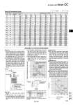
Converter Air-hydro unit Pressure inside the cylinder Pneumatic speed controller for fast-forward speed control (AS420, AS500) Control direction Pressure inside the cylinder 0.5 MPa Pressure inside 0.3 MPa CCVL1. CCVS1. CCVS3. Piston rod movement during 15 sec. (mm) Jumping (mm) Bore size (mm) Bore size (mm) Skip valve 1. When using a skip valve, the maximum allowable ratio between the high speed and the low speed is approximately 3:1. If this ratio is too large, air bubbles could form due to cavitations, and could lead to the conditions described in the single-side hydro 1), 2), 3), and 4) of the Product Specific Precautions (page 1164). 2. If the skip valve of an air-hydro unit with skip valve is operated, because it is not equipped with a speed control valve, the fast-forward speed will be determined by the model, piping conditions, and the actuator used. In this case, the cylinder could operate at extremely high speeds if the cylinder bore size is small. If it is necessary to control the fast forward speed, use a pneumatic speed controller as shown in Fig. (3). 3. If the cylinder is operated facing up, when the stop valve that is provided on the rod side is closed, the piston rod could descend when the pressure on the head side is turned to zero. To prevent this, a stop valve must also be provided on the head side. 4. Because the stop valve uses a metal seal, it has a slight leak. Due to this leakage, the cylinder could move in the amount that is shown in the Fig. (4), after making an intermediate stop. Stop valve 1. Operate the stop valve under meter-out control. 2. If the movement must be stopped at an intermediate position in both directions through the use of a stop valve, make sure to provide a stop valve for both the head side and the rod side. Surge pressure When the cylinder is operated at high speeds and reaches the stroke end, surge pressure could be created in the rod side or in the head side. At this time, if the stop valve of the rod side or the head side is closed, the surge pressure could become sealed in, preventing the stop valve from operating. This can be solved by closing the stop value 1 to 2 seconds later. Temperature rise When the cylinder is stopped at the stroke end, a speed control valve located opposite to the stroke end (which is the stop valve on the rod cover during retraction, and the stop valve on the head cover during extension) remains closed, the cylinderüfs internal pressure could increase with temperature, preventing the stop valve from opening. Therefore, do not close the stop valve in this condition. Jumping of pressure compensating mechanism Be aware that the amount of jumping that is shown in Fig. (5) applies to the pressure compensation mechanism during the operation of the cylinder. ügJumpingüh is a condition in which the cylinder operates without control at a speed that is higher than the control speed. Fig. (3) Fig. (4) Data (D) Theoretical Output Bore size (mm) Piston area (mm2) Rod size (mm) Operating direction Operating pressure (MPa) (N) OUT IN OUT IN OUT IN OUT IN OUT IN OUT IN OUT IN OUT IN OUT IN OUT IN OUT IN OUT IN OUT IN OUT IN OUT IN 20 25 32 40 50 63 80 100 125 140 160 180 200 250 300 8 10 12 14 20 20 25 30 36 36 40 45 50 60 70 314 264 491 412 804 691 1260 1100 1960 1650 3120 2800 5030 4540 7850 7150 12300 11300 15400 14400 20100 18800 25400 23900 31400 29500 49100 46300 70700 66800 0.2 62.8 52.8 98.2 82.4 161 138 252 220 392 330 624 560 1010 908 1570 1430 2460 2260 3080 2880 4020 3760 5080 4780 6280 5900 9820 9260 14100 13400 0.3 94.2 79.2 147 124 241 207 378 330 588 495 936 840 1510 1360 2360 2150 3690 3390 4620 4320 6030 5640 7620 7170 9420 8850 14700 13900 21200 20000 0.4 126 106 196 165 322 276 504 440 784 660 1250 1120 2010 1820 3140 2860 4920 4520 6160 5760 8040 7520 10200 9560 12600 11800 19600 18500 21200 26700 0.5 157 132 246 206 402 346 630 550 980 825 1560 1400 2520 2270 3930 3580 6150 5650 7700 7200 10100 9400 12700 12000 15700 14800 24600 23200 35400 33400 0.6 188 158 295 247 482 415 756 660 1180 990 1870 1680 3020 2720 4710 4290 7380 6780 9240 8640 12100 11300 15200 14300 18800 17700 29500 27800 42400 40100 0.7 220 185 344 288 563 484 882 770 1370 1160 2180 1960 3520 3180 5500 5010 8610 7910 10800 10100 14100 13200 17800 16700 22000 20700 34400 32400 49500 46800 0.8 251 211 393 330 643 553 1010 880 1570 1320 2500 2240 4020 3630 6280 5720 9840 9040 12300 11500 11500 15000 20300 19100 25100 23600 39300 37000 56600 53400 0.9 283 238 442 371 724 622 1130 990 1760 1490 2810 2520 4530 4090 7070 6440 11100 10200 13900 13000 18100 16900 22900 21500 28300 26600 44200 41700 63600 60100 1.0 314 264 491 412 804 691 1260 1100 1960 1650 3120 2800 5030 4540 7850 7150 12300 11300 15400 14400 20100 18800 25400 23900 31400 29500 49100 46300 70700 66800 OUT IN 5. For response time of stop valve, refer to the list below. Model CCVS CCVL Response time 0.07 ü} 0.015 sec. 0.11 ü} 0.02 sec. Intermediate stop accuracy of CCVS: 50 mm/s x ü}0.015 sec. = ü}0.75 mm in case of 50 mm/s Fig. (5) Caution on Circuit Construction Air-hydro Unit Series CC Pressure inside the cylinder 0.7 MPa the cylinder 1155 CC D-« -X« Technical data