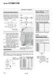
CY3B50,63 CY3B25,32,40 CY3B20 CY3B15 CY3𡱖6 CY3𡱖10 CY3𡱖15 CY3𡱖6 CY3B10 CY3𡱖63 CY3𡱖50 CY3𡱖40 CY3𡱖32 CY3𡱖25 CY3𡱖20 Cylinder Dead Weight Deflection Vertical Operation When the cylinder is mounted horizontally, deflection appears due to its own weight as shown in the data, and the longer the stroke is, the greater the amount of variation in the shaft center. Therefore, a connection method should be considered which can assimilate this deflection. It is recommended that the load is guided by a ball type bearing (linear guide, etc.). If a slide bearing is used, sliding resistance increases due to the load mass and moment, which may cause malfunctions. When the cylinder is mounted vertically or sidelong, a slider may move downwards due to the selfweight or workpiece mass. If an accurate stopping position is required at the stroke end or midstroke, use an external stopper to secure accurate positioning. Guide shaft Load platform Clearance (Note) (0.2 to 0.5 mm) Load mass (Slider bracket weight + Workpiece mass) Workpiece Rodless cylinder CY3B CY3R W C Precautions on Design 2 (Note) Maximum Load Mass when Loaded Directly on Body When the load is applied directly to the body, it should be no greater than the maximum values shown in the table below. Model CY3R6 CY3R10 CY3R15 CY3R20 CY3R25 CY3R32 CY3R40 CY3R50 CY3R63 0.2 0.4 1.0 1.1 1.2 1.5 2.0 2.5 3.0 Max. load weight (WBmax) (kg) Loading direction Switch rail Wear ring C Body Loading direction Bore size (mm) Model Allowable load mass (Wv) (kg) Max. operating pressure (Pv) (MPa) 6 10 15 20 25 32 40 50 63 CY3𡱖6 CY3𡱖10 CY3𡱖15 CY3𡱖20 CY3𡱖25 CY3𡱖32 CY3𡱖40 CY3𡱖50 CY3𡱖63 1.0 2.7 7.0 11.0 18.5 30.0 47.0 75.0 115.0 0.55 0.55 0.65 0.65 0.65 0.65 0.65 0.65 0.65 The above clearance amount is a reference value. Note 1) According to the dead weight deflection in the figure on the right, provide clearance so that the cylinder does not touch the mounting surface or the load, etc., and is able to operate smoothly within the minimum operating pressure range for a full stroke. For more information, refer to instruction manual. Note 2) In case of the CY3R, install a shim, etc. to eliminate clearance between the body and the switch rail. For more information, refer to the CY3R instruction manual. Note 3) The amount of deflection differs from the CY1B/CY1R. Adjust the clearance value by referring to the dead weight deflection as shown in the table on the right. When CY1B/CY1R are replaced with CY3B/CY3R, install a cylinder after confirming a full stroke and clearance are allowed. Maximum Weight of Connection Bracket to the Body Series CY3B is guided by an external axis (such as a linear guide) without directly mounting the load. When designing a metal bracket to connect the load, make sure that its weight will not exceed the value in the table below. Basically, guide the CY3R direct mounting type also with an external axis. (For connection methods, refer to the Instruction Manual.) Model CY3𡱖6 CY3𡱖10 CY3𡱖15 CY3𡱖20 CY3𡱖25 CY3𡱖32 CY3𡱖40 CY3𡱖50 CY3𡱖63 0.2 0.4 1.0 1.1 1.2 1.5 2.0 2.5 3.0 Max. connection bracket weight (WBmax) (kg) Max. Connection Bracket Weight Consult with SMC in case a bracket with weight exceeding the above value is to be mounted. 28 27 26 25 24 23 22 21 20 19 18 17 16 15 14 13 12 11 10 9876543210 1000 2000 3000 4000 5000 6000 Deflection (mm) Stroke (mm) . Use caution, as there is a danger of breaking the magnetic coupling if operated above the maximum operating pressure. . The above deflection data represent values at the time when the external sliding part moves to the middle of the stroke. Series CY3B/CY3R 1450