3-p0337-0408-mgp_en 26 / 73
10秒後にBOOKのページに移動します
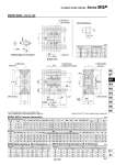
MGPM, MGPL: o32 to o63 傱 Choice of Rc, NPT, G port is possible. (Refer to page 346.) 傱 For intermediate strokes other than standard strokes, refer to “Manufacture of Intermediate Stroke” on page 347. B 32 40 50 63 Standard stroke (mm) Bore size (mm) 32 40 50 63 Bore size (mm) MGPL (Ball bushing bearing) A, DB, E Dimensions 59.5 66 72 77 C 37.5 44 44 49 DA 16 16 20 20 FA 12 12 16 16 FB 10 10 12 12 G 48 54 64 78 GA 12.5 14 14 16.5 GB 9 10 11 13.5 H 112 120 148 162 HA M6 M6 M8 M10 J 24 27 32 39 K 24 27 32 39 L 34 40 46 58 MM M8 x 1.25 M8 x 1.25 M10 x 1.5 M10 x 1.5 ML 20 20 22 22 NN M8 x 1.25 M8 x 1.25 M10 x 1.5 M10 x 1.5 OA 6.6 6.6 8.6 8.6 OB 11 11 14 14 OL 7.5 7.5 9 9 Rc 1/8 Rc 1/8 Rc 1/4 Rc 1/4 NPT 1/8 NPT 1/8 NPT 1/4 NPT1/4 G 1/8 G 1/8 G 1/4 G 1/4 Nil N TF P 25, 50, 75 100, 125, 150 175, 200, 250 300, 350, 400 Q 32 40 50 63 Bore size (mm) 30 30 40 50 PW 35.5 39.5 47 58 PB 15 18 21.5 28 PA 7 13 9 14 R 96 104 130 130 S 44 44 60 70 T 110 118 146 158 U 78 86 110 124 VA 98 106 130 142 VB 63 72 92 110 24 24 24 28 48 48 48 52 124 124 124 128 200 200 200 200 300 300 300 300 WA 33 34 36 38 45 46 48 50 83 84 86 88 121 122 124 124 171 172 174 174 WB X 42 50 66 80 XA 4 4 5 5 XB 4.5 4.5 6 6 XC 3 3 4 4 XL 6 6 8 8 YL 16 16 20 20 Z 21 22 24 24 A E DB 81 81 93 93 98 98 114 114 118 118 134 134 140 140 161 161 16 16 20 20 21.5 15 21 16 38.5 32 42 37 58.5 52 62 57 80.5 74 89 84 MGPM, MGPL Common Dimensions 32 40 50 63 Bore size (mm) MGPM (Slide bearing) A, DB, E Dimensions A E DB 97 97 106.5 106.5 102 102 118 118 140 140 161 161 20 20 25 25 37.5 31 34.5 29.5 42.5 36 46 41 80.5 74 89 84 M8 x 1.25 M8 x 1.25 M10 x 1.5 M10 x 1.5 YY 25 st or less Over 200 st Over 300 st to 300 st Over 100 st to 200 st Over 25 st to 100 st 25 st or less Over 300 st Over 200 st to 300 st Over 100 st to 200 st Over 25 st to 100 st 50 st or less Over 100 st Over 200 st to 200 st Over50 st to 100 st 50 st or less Over 200 st Over 100 st to 200 st Over 50 st 50 st or less Over 200 st to 100 st Over 50 st 50 st or less Over 200 st to 200 st Over 50 st to 200 st Compact Guide Cylinder Series MGP (mm) (mm) (mm) 32 40 50 63 a 6.5 6.5 8.5 11 b 10.5 10.5 13.5 17.8 c 5.5 5.5 7.5 10 d 3.5 4 4.5 7 e 9.5 11 13.5 18.5 Bore size (mm) T-slot dimensions (mm) 2 x P 2 x P (Plug) 4 x YY depth YL oXA H 7 depth XL Section XX Section XX 4 x MM depth ML oXA H 7 depth XL 4 x oOA through Section XX 4 x oOB counterbore depth OL 4 x NN through oXA H 7 depth XL Detailed figure of XX section Bottom view T-slot dimensions e c d a b (OL) L X X±0.02 Z WA WB XC XL XB oXAH7 XAH7 X±0.02 T Q R S oDB oDA E GB U X Z WA PW H VA VB G PB X±0.02 J K FA FB GA HA: T-slot for hexagon bolt PA + Stroke C + Stroke B + Stroke A + Stroke 361 MGJ MGP -Z MGP MGPW MGQ MGG MGC MGF MGZ MGT D-𡱖 -X𡱖