3-p0337-0408-mgp_en 30 / 73
10秒後にBOOKのページに移動します
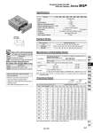
Symbol Air cushion -XC19 -XC79 Intermediate stroke (Spacer type) Machining tapped hole, drilled hole and pin hole additionally. Symbol Specifications -X144 -X867 Symmetrical port position Lateral piping type (Change of plug position) Symbol Specifications Bore size o16 o20 o25 o32 o40 o50 o63 o80 o100 Action Fluid Proof pressure Maximum operating pressure Bore size (mm) Rod size (mm) Operating direction Piston area (mm2) Operating pressure (MPa) 0.2 0.3 0.4 0.5 0.6 0.7 0.8 0.9 1.0 Note) Theoretical output (N) = Pressure (MPa) x Piston area (mm2) Minimum operating pressure Ambient and fluid temperature Piston speed Cushion Lubrication Stroke length tolerance Double acting Air 1.5 MPa 1.0 MPa 0.15 MPa 0.12 MPa 50 to 500 mm/s 50 to 400 mm/s Air cushion on both ends (Without bumper) Not required (Non-lube) (mm) .10 to 60°C (No freezing) +1.5 0 16 20 25 32 40 50 63 80 100 OUT IN OUT IN OUT IN OUT IN OUT IN OUT IN OUT IN OUT IN OUT IN 201 151 314 236 491 378 804 603 1257 1056 1963 1649 3117 2803 5027 4536 7854 7147 40 30 63 47 98 76 161 121 251 211 393 330 623 561 1005 907 1571 1429 60 45 94 71 147 113 241 181 377 317 589 495 935 841 1508 1361 2356 2144 80 60 126 94 196 151 322 241 503 422 785 660 1247 1121 2011 1814 3142 2859 101 76 157 118 246 189 402 302 629 528 982 825 1559 1402 2514 2268 3927 3574 121 91 188 142 295 227 482 362 754 634 1178 990 1870 1682 3016 2722 4712 4288 141 106 220 165 344 265 563 422 880 739 1374 1154 2182 1962 3519 3175 5498 5003 161 121 251 189 393 302 643 482 1006 845 1570 1319 2494 2242 4022 3629 6283 5718 181 136 283 212 442 340 724 543 1131 950 1767 1484 2805 2523 4524 4082 7069 6432 201 151 314 236 491 378 804 603 1257 1056 1963 1649 3117 2803 5027 4536 7854 7147 8 10 12 16 16 20 20 25 30 Specifications Standard Stroke Bore size (mm) Standard stroke (mm) 25, 50, 75, 100, 125, 150, 175, 200, 250 25, 50, 75, 100, 125, 150, 175, 200, 250, 300, 350, 400 50, 75, 100, 125, 150, 175, 200, 250, 300, 350, 400 o16 o20 to o63 o80, o100 16 20 to 63 80, 100 15 to 249 15 to 399 20 to 399 Manufacture of Intermediate Stroke Theoretical Output Description Part no. Suffix “-XC19” to the end of standard part number. Example Applicable stroke (mm) Model: MGPM20-35A-XC19 A collar 15 mm in width is installed in a MGPM20-50A C dimension is 112 mm. Refer to pages 404 to 406 for cylinders with auto switches. Note) Intermediate stroke (by the 1 mm interval) based on an exclusive body will be available upon request for special. Intermediate strokes by the 1 mm interval are available by replacing collars of a standard stroke cylinder. Minimum manufacturable stroke o16 to o63: 15 mm o80, o100: 20 mm Select a rubber bumper type, because the cushion effect is not obtainable for less than this stroke. Minimum auto switch mounting stroke Proper auto switch mounting position (detection at stroke end) and mounting height Operating range Auto switch mounting bracket: Part no. Series MGP Compact Guide Cylinder With Air Cushion Made to Order: Individual Specifications (For details, refer to pages 407 and 408.) Made to Order Specifications (For details, refer to pages 2009 to 2152.) OUT(N) IN(N) (N) 365 MGJ MGP -Z MGP MGPW MGQ MGG MGC MGF MGZ MGT D- -X