3-p0337-0408-mgp_en 32 / 73
10秒後にBOOKのページに移動します
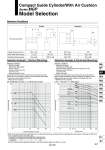
L m 5 10 50 5 1 0.1 10 20 25 26 50 100 200 Stroke (mm) Load mass m (kg) Load mass m (kg) o50,63 o100 o80 o50,63 o32 o40 o20 o16 o40 o32 o25 o20 o16 o25 10 20 1 10 50 100 200 Eccentric distance L (mm) o25 o20 o16 L L m m L m Selection Conditions Selection Example 1 (Vertical Mounting) Selection Example 2 (Horizontal Mounting) Mounting orientation Vertical Horizontal Maximum speed (mm/s) Graph (Slide bearing type) Graph (Ball bushing bearing type) (5) 75 Stroke or Less, V = 200 mm/s or less (17) L = 50 mm, V = 400 mm/s 200 or less (1), (2) (5) to (9) 400 (3), (4) (10) to (14) 200 or less (15), (16) (19), (20) 400 (17), (18) (21), (22) Selection conditions Mounting: Vertical Bearing type: Ball bushing Stroke: 75 stroke Maximum speed: 200 mm/s Load mass: 7 kg Eccentric distance: 70 mm Find the point of intersection for the load mass of 7 kg and the eccentric distance of 70 mm on graph (5), based on vertical mounting, ball bushing, 75 mm stroke, and the speed of 200 mm/s. MGPL25-75A is selected. Selection conditions Mounting: Horizontal Bearing type: Slide bearing Distance between plate and load center of gravity: 40 mm Maximum speed: 400 mm/s Load mass: 8 kg Stroke: 100 stroke Find the point of intersection for the load mass of 8 kg and 100 stroke on graph (17), based on horizontal mounting, slide bearing, the distance of 40 mm between the plate and load center of gravity, and the speed of 400 mm/s. MGPM32-100A is selected. . When the maximum speed exceeds 200 mm/s, the allowable load mass is determined by multiplying the value shown in the graph at 400 mm/s by the coefficient listed in the table below. Up to 300 mm/s 1.7 Up to 400 mm/s 1 Up to 500 mm/s 0.6 Maximum Coefficient Compact Guide Cylinder/With Air Cushion Series MGP Model Selection . Use the “Guide Cylinder Selection Software”, when the eccentric distance is 200 mm or more. 367 MGJ MGP -Z MGP MGPW MGQ MGG MGC MGF MGZ MGT D- -X