3-p0337-0408-mgp_en 42 / 73
10秒後にBOOKのページに移動します
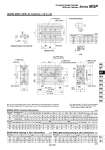
MGPM, MGPL (With Air Cushion): o16 to o25 16 20 25 a 4.4 5.4 5.4 b 7.4 8.4 8.4 c 3.7 4.5 4.5 d 2.5 2.8 3 e 6.7 7.8 8.2 T-slot dimensions T-slot dimensions 16 20 25 Bore size (mm) MGPM (Slide bearing) A, DB, E Dimensions A DB 71 78 78.5 25 st 89.5 86.5 87 50 st 71 84.5 85 75,100 st 95 84.5 85 125 to 200 st 95 122 122 250 st or more 10 12 16 C 16 20 25 Standard stroke (mm) Bore size (mm) 58 62 62.5 B 71 78 78.5 CV . 1.5 1.5 DA 8 10 12 FA 8 10 10 FB 5 6 6 G 30 36 42 GA 11 10.5 11.5 GB 8 8.5 9 H 64 83 93 HA M4 M5 M5 J 15 18 21 K 15 18 21 L 22 24 30 MM M5 x 0.8 M5 x 0.8 M6 x 1.0 ML 12 13 15 NN M5 x 0.8 M5 x 0.8 M6 x 1.0 OA 4.3 5.4 5.4 OB 8 9.5 9.5 OL 4.5 5.5 5.5 75 st or less 25, 50, 75, 100, 125, 150, 175, 200, 250 25, 50, 75, 100, 125, 150, 175 200, 250, 300, 350, 400 Q 16 20 25 Bore size (mm) 16 18 26 PW 19 25 30 PB 10 10.5 13.5 PA 40 37.5 37.5 R 54 70 78 S 25 30 38 T 62 81 91 U 46 54 64 VA 56 72 82 VB 38 44 50 44 44 44 100 to 175 st 110 120 120 200, 250 st 200 200 200 300 st or more . 300 300 75 st or less 27 39 39 100 to 175 st 60 77 77 200, 250 st 105 117 117 300 st or more . 167 167 WA WB X 24 28 34 XA 3 3 4 XB 3.5 3.5 4.5 YL 10 12 12 Z 5 17 17 MGPM, MGPL Common Dimensions M5 x 0.8 M6 x 1.0 M6 x 1.0 YY M5 x 0.8 Rc 1/8 Rc 1/8 . NPT 1/8 NPT 1/8 . G 1/8 G 1/8 Nil N TF P E 0 0 0 25 st 18.5 8.5 8.5 50 st 0 6.5 6.5 75,100 st 24 6.5 6.5 125 to 200 st 24 44 43.5 250 st or more 16 20 25 Bore size (mm) MGPL (Ball bushing bearing) A, DB, E Dimensions A DB 80 95 100.5 25 st 71 80 85.5 50, 75 st 71 99 104.5 100 st 95 104 104.5 125 to 200 st 95 122 122 250 st or more 8 10 13 E 9 17 22 25st 0 2 7 50, 75st 0 21 26 100st 24 26 26 125 to 200st 24 44 43.5 250 st or more Bore size (mm) For bore size wlth o 16, M5 x 0.8 is only available. Rc, NPT, G port can be selected for bore sizes with o20 or more. (Refer to page 364.) Note 1) For the intermediate strokes, refer to “Manufacture of Intermediate Stroke” on page 365. Note 2) When adjusting the o16 cushion valve, use a 3 mm flat head watchmakers’ screwdriver. (mm) (mm) (mm) (mm) Series MGP Compact Guide Cylinder With Air Cushion oXAH7 depth 6 4 x YY depth YL Section XX 2 x cushion valve (Width across flats CV) 4 x NN through oXAH7 depth 6 Section XX 2 x P (Plug) Section XX 4 x MM depth ML oXAH7 depth 6 4 x oOA through 4 x oOB counterbore depth OL 2 x P Detailed figure of section XX 3 Z X ±0.02 X WB WA XAH7 oXAH7 3 XB 6 e b a c d Bottom view (OL) X ±0.02 oDA FB X ±0.02 R T Q S PB J K G L H VA VB HA: T-slot for hexagon bolt oDB WA GB GA PA + Stroke C + Stroke B + Stroke E A + Stroke FA Z U X PW o16 377 MGJ MGP -Z MGP MGPW MGQ MGG MGC MGF MGZ MGT D- -X