3-p0337-0408-mgp_en 51 / 73
10秒後にBOOKのページに移動します
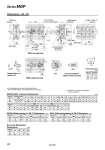
Dimensions: o20, o25 B C DA G GA GB H J L MM ML N TF PB P PW Q R S T U VA VB WB X XA XB WA 20 25 20 25 Standard stroke (mm) Bore size (mm) Bore size (mm) MGPM, MGPL Common Dimensions MGPM (Slide bearing) A, DB, E Dimensions MGPL (Ball bushing bearing) A, DB, E Dimensions 78 78.5 62 62.5 81 91 10 12 54 64 36 42 72 82 44 50 10.5 11.5 8.5 9 18 21 18 21 24 30 Rc 1/8 Rc 1/8 M5 x 0.8 M6 x 1.0 G 1/8 G 1/8 NPT 1/8 NPT 1/8 70 78 18 26 25 30 10.5 13.5 30 38 28 34 3 4 3.5 4.5 25, 50, 75, 100, 125 150, 175, 200, 250 300, 350, 400 NN M5 x 0.8 M6 x 1.0 Nil 13 15 K 83 93 44 44 120 120 75 st or less 300 300 Over 75 st to 175 st Over 250 st 200 200 Over 175 st to 250 st 75 st or less Over 75 st to 175 st Over 250 st Over 175 st to 250 st 39 39 77 77 167 167 117 117 A E DB 20 25 80 85.5 104 104.5 26 26 2 7 10 13 122 122 A E DB 20 25 78 78.5 84.5 85 0 0 6.5 6.5 12 16 25 st or less 122 122 Over 175 st 44 43.5 Over 25 st to 175 st 25 st or less Over 25 st Over 175 st to 175 st 75 st or less Over 175 st Over 75 st to 175 st 75 st or less Over 175 st Over 75 st to 175 st Bore size (mm) Bore size (mm) 44 43.5 End Lock Mechanism Dimensions DL 20 25 21 26.5 DM 19 16 HR 10.5 8 HN 22 19.5 Bore size (mm) For intermediate strokes other than standard strokes, refer to the Manufacture of Intermediate Stroke on page 382. Rc, NPT and G ports can be selected. (Refer to page 381.) (mm) (mm) (mm) (mm) Series MGP T-slot dimensions 20 25 2.8 3 7.8 8.2 d e Bore size T-slot dimensions (mm) (mm) Section XX Section XX Section XX 4 x NN through 4 x MM depth ML 4 x M6 x 1.0 depth 12 2 x P 2 x P (Plug) oXAH7 depth 6 oXAH7 depth 6 oXAH7 depth 6 4 x o5.4 through 4 x o9.5 counterbore depth 5.5 End lock mechanism Manual release Non-lock type Detailed figure of section XX End lock mechanism (Manual release lock type) o25 With rod end lock With head end lock XAH7 6 3 XB oXAH7 e 4.5 d 5.4 8.4 HN o15 DL 15 24 DM 24 HR 15 o11 24 R (5.5) oDB A + Stroke PB L 37.5 + Stroke H VA E VB M5:T-slot for hexagon bolt PW X U 17 WA oDA X ±0.02 T X WB WA 17 J K G QS B + Stroke 10 6 C + Stroke GB GA X ±0.02 X ±0.02 386