3-p0337-0408-mgp_en 52 / 73
10秒後にBOOKのページに移動します
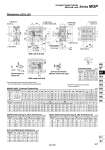
Dimensions: o32 to o63 FA FB G GA GB H HA J L MM ML OL N TF P PA PB PW Q X XA 32 40 50 63 32 40 50 63 Standard stroke (mm) Bore size (mm) Bore size (mm) MGPM, MGPL Common Dimensions MGPM (Slide bearing) A, DB, E Dimensions MGPL (Ball bushing bearing) A, DB, E Dimensions 12 12 16 16 DA 16 16 20 20 C 62.5 69 69 74 B 10 10 12 12 32 38 34 39 48 54 64 78 15 18 21.5 28 12.5 14 14 16.5 35.5 39.5 47 58 30 30 40 50 R 96 104 130 130 S 44 44 60 70 T 110 118 146 158 U 78 86 110 124 VA 98 106 130 142 VB 63 72 92 110 9 10 11 13.5 112 120 148 162 24 27 32 39 24 27 32 39 34 40 46 58 Rc1/8 Rc1/8 Rc1/4 Rc1/4 M8 x 1.25 M8 x 1.25 M10 x 1.5 M10 x 1.5 G1/8 G1/8 G1/4 G1/4 NPT1/8 NPT1/8 NPT1/4 NPT1/4 7.5 7.5 9 9 OB 11 11 14 14 OA 6.6 6.6 8.6 8.6 42 50 66 80 4 4 5 5 XB 4.5 4.5 6 6 XC 3 3 4 4 XL 6 6 8 8 YY M8 x 1.25 M8 x 1.25 M10 x 1.5 M10 x 1.5 YL 16 16 20 20 Z 21 22 24 24 25, 50, 75 100, 125, 150 175, 200, 250 300, 350, 400 NN M8 x 1.25 M8 x 1.25 M10 x 1.5 M10 x 1.5 Nil 20 20 22 22 K M6 M6 M8 M10 WA WB 48 48 48 52 124 124 124 128 300 300 300 300 200 200 200 200 45 46 48 50 83 84 86 88 171 172 174 174 121 122 124 124 A E DB 32 40 50 63 84.5 91 97 102 98 98 114 114 0 0 0 0 16 16 20 20 140 140 161 161 118 118 134 134 A E DB 32 40 50 63 97 97 106.5 106.5 102 102 118 118 12.5 6 9.5 4.5 17.5 11 21 16 20 20 25 25 140 140 161 161 55.5 49 64 59 Bore size (mm) Bore size (mm) 55.5 49 64 59 End Lock Mechanism Dimensions DL 32 40 50 63 22 26 24 25 DM 22 23 23 25.5 HR 9.5 11.5 13 11 HN 21 25.5 27 25 LL 15 21 21 21 MO 15 19 19 19 Bore size (mm) For intermediate strokes other than standard strokes, refer to the Manufacture of Intermediate Stroke on page 382. Rc, NPT and G ports can be selected. (Refer to page 381.) T-slot dimensions Detailed figure of section XX End lock mechanism (Manual release lock type) With rod end lock With head end lock 32 40 50 63 6.5 6.5 8.5 11 a 10.5 10.5 13.5 17.8 b 5.5 5.5 7.5 10 c 3.5 4 4.5 7 d 9.5 11 13.5 18.5 e 13.5 7 17 12 33.5 27 37 32 84.5 91 97 102 Bore size T-slot dimensions (mm) 75 st or less Over 75 st to 175 st Over 250 st Over 175 st to 250 st 75 st or less Over 75 st to 175 st Over 250 st Over 175 st to 250 st 25 st or less 25 st or less Over 25 st to 75 st Over 25 st to 175 st Over 175 st Over 25 st or less 175 st Over 25 st to 175 st Over 175 st Over 75 st to 175 st 25 st or less Over 25 st to 75 st Over 175 st Over 75 st to 175 st (mm) (mm) (mm) (mm) (mm) Series MGP Compact Guide Cylinder With End Lock Section XX Section XX Section XX oXAH7 depth XL 2 x P oXAH7 depth XL 4 x NN through oXAH7 depth XL 2 x P (Plug) 4 x MM depth ML 4 x YY depth YL End lock mechanism Manual release Non-lock type 4 x oOA through 4 x oOB counterbore depth OL XL XC XB e c d a b HN oMO HR 24 o11 DL LL DM LL WB WA Z X (OL) oDB Z WA L PB J K E G FAFB Q GA GB S H VA VB U X PW oDA T R X ±0.02 X ±0.02 PA + Stroke C + Stroke B + Stroke A + Stroke X ±0.02 XAH7 oXAH7 HA: T-slot for hexagon bolt 387 MGJ MGP -Z MGP MGPW MGQ MGG MGC MGF MGZ MGT D- -X