3-p0337-0408-mgp_enЃ@Ѓ@Ѓ@57 / 73
10•bЊг‚ЙBOOK‚МѓyЃ[ѓW‚Й€Ъ“®‚µ‚Ь‚·
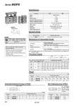
-X867 Lateral piping type (Change of plug position) Symbol Specifications Symbol Rubber bumper o50 o80 Specifications Description Part no. Applicable stroke (mm) Example Action Fluid Proof pressure Maximum operating pressure Minimum operating pressure Ambient and fluid temperature Piston speed Cushion Lubrication Stroke length tolerance Double acting Air 1.5 MPa 1.0 MPa 0.1 MPa .10 to 60Ѓ‹C (No freezing) 50 to 400 mm/s Rubber bumper on both ends Not required (Non-lube) +1.5 mm 0 Bore size (mm) Standard stroke (mm) 50, 80 25, 50, 75, 100, 125, 150, 175, 200 Spacer installation type Spacers are installed in the standard stroke cylinder. Available by the 5 mm stroke interval. Part no.: MGPS50-35 A spacer 15 mm in width is installed in a MGPS50-50. C dimension is 94 mm. Refer to ЃgHow to OrderЃh for the standard model numbers on page 391. 5 to 195 Standard Stroke Manufacture of Intermediate Stroke Theoretical Output Allowable Rotational Torque of Plate Rod size (mm) Piston area (mm2) Operating pressure (MPa) 50 1963 1649 5027 4536 0.2 393 330 1005 907 Note) Theoretical output (N) = Pressure (MPa) x Piston area (mm2) 0.3 589 495 1508 1361 0.4 785 660 2011 1814 0.5 982 825 2513 2268 0.6 1178 990 3016 2721 0.7 1374 1155 3519 3175 0.8 1571 1319 4021 3629 0.9 1767 1484 4524 4082 1.0 1963 1649 5027 4536 OUT IN OUT IN Operating direction Bore size (mm) 80 20 25 OUT IN Bore size (mm) Standard stroke (mm) 25 15 49 MGPS50 MGPS80 Model 50 80 50 12 41 75 16 51 100 15 45 125 13 41 150 12 38 175 11 35 200 9.8 32 Bore size (mm) MGPS50 MGPS80 Model 50 80 Non-rotating accuracy ѓЖ Ѓ}0.05Ѓ‹ Ѓ}0.04Ѓ‹ Torque: T (NЃEm) +ѓЖ . ѓЖ T (N.m) (N) Weight MGPS50 MGPS80 Bore size Model (mm) 25 3.90 9.21 Standard stroke (mm) 50 80 50 4.68 10.7 75 5.74 13.0 100 6.52 14.5 125 7.30 15.9 150 8.08 17.9 175 8.86 18.9 200 9.64 20.3 (kg) Non-rotating Accuracy of Plate Refer to pages 404 to 406 for cylinders with auto switches. Bore size Note) Intermediate stroke (by the 1 mm interval) based on an exclusive body will be available upon request for special. For non-rotating accuracy ѓЖ without load, use a value no more than the values in the table as a guide. р‘ Minimum auto switch mounting stroke р‘ Proper auto switch mounting position (detection at stroke end) and mounting height р‘ Operating range р‘ Auto switch mounting bracket: Part no. Made to Order: Individual Specifications (For details, refer to page 408.) Series MGPS 392