3-p0337-0408-mgp_en 9 / 73
10秒後にBOOKのページに移動します
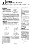
Warning Caution Bore size (mm) A (mm) B (mm) C (mm) 12 16 20 25 32 40 50 63 80 100 D MGPM MGPL Hexagon socket head cap screw 50 56 72 82 98 106 130 142 180 210 18 22 24 30 34 40 46 58 54 62 41 46 54 64 78 86 110 124 156 188 10 12 14 18 22 22 27 27 33 39 8 10 12 15 18 18 22 22 28 33 M4 x 0.7 M5 x 0.8 M5 x 0.8 M6 x 1.0 M8 x 1.25 M8 x 1.25 M10 x 1.5 M10 x 1.5 M12 x 1.75 M14 x 2.0 (mm) Series MGP Bore size (mm) A (mm) B (mm) C (mm) 50 80 Hexagon socket head cap screw 140 214 50 66 116 170 M12 x 1.75 M16 x 2 Series MGPS D (mm) 32 47 Bore size (mm) 16 20,25,32,40 50,63 80,100 Applicable tool Flat head watchmakers , screwdriver 3 mm JIS B 4648 hexagon wrench key 1.5 JIS B 4648 hexagon wrench key 2.5 JIS B 4648 hexagon wrench key 4 Mounting Cushion 1/8 1/4 3/8 7 to 9 12 to 14 22 to 24 Connection thread (plug) size Proper tightening torque (N・m) 0.5 mm or less 1 mm or less 1 mm or less a dimension a Plug 1. Never place your hands or fingers between the plate and the body. Be very careful to prevent your hands or fingers from getting caught in the gap between the cylinder body and the plate when air is applied. 1. Use cylinders within the piston speed range. An orifice is set for this cylinder, but the piston speed may exceed the operating range if the speed controller is not used. If the cylinder is used outside the allowable speed range, it may cause damage to the cylinder and shorten the service life. Adjust the speed by installing the speed controller and use the cylinder within the limited range. 2. Do not scratch or gouge the sliding portion of the piston rod and the guide rod. Damaged seals, etc. will result in leakage or malfunction. 3. Do not dent or scratch the mounting surface of a body and a plate. The flatness of the mounting surface may not be maintained, which would cause an increase in sliding resistance. 4. Make sure that the cylinder mounting surface has a flatness of 0.05 mm or less. If the flatness of the workpieces and brackets mounted on the plate is not appropriate, sliding resistance may increase. 5. Bottom of cylinder The guide rods protrude from the bottom of the cylinder at the end of the retracting stroke, and therefore, in cases where the cylinder is to be bottom mounted, it is necessary to provide bypass ports in the mounting surface for the guide rods, as well as holes for the hexagon socket head screws which are used for mounting. Moreover, in applications where impact occurs from a stopper, etc., the mounting bolts should be inserted to a depth of 2 d or more (1.5 d or more for MGPS). Warning With air cushion 1. Do not open the cushion valve excessively. Air leakage will occur if operated after opening by 4 rotations or more. Furthermore, a stopper mechanism is provided for the cushion valve, and it should not be forced open beyond that position. Be aware that the cushion valve may jump up from the cover when the air is supplied. Caution 1. Be sure to use the cylinder after the air cushion has been adjusted appropriately. First, fully close the cushion valve. Start the operation at the cylinder speed to be used with the load applied, and then open the cushion valve gradually to make the adjustment. The optimal adjustment is that the piston reaches its stroke end and the collision sound is minimized. If the cushion valve is used without adjusting the air cushion appropriately, this may cause damage to the retaining ring or piston. 2. Be sure to operate a cylinder equipped with air cushion to the end of the stroke. If it is not operated to the end of the stroke, the effect of the air cushion will not be fully exhibited. Consequently, in cases where the stroke is regulated by an external stopper, etc., caution must be exercised, as the air cushion may become completely ineffective. Piping Caution Depending on the operating conditions, piping port positions can be changed by using a plug. 1. For M5 After tightening by hand, tighten additional 1/6 to 1/4 rotation with a tightening tool. 2. For taper thread Use the correct tightening torques listed below. Before tightening the plug, wrap pipe tape around it. Also, with regard to the sunk dimension of a plug (a dimension in the drawing), use the stipulated figures as a guide and confirm the air leakage before operation. . If tightening plugs on the top mounting port with more than the proper tightening torque, plugs will be screwed much deeply and air passage will be squeezed. Consequently, the cylinder speed will be restricted. Series MGP Specific Product Precautions 1 C±0.2 A±0.2 oD Bypass port dia. B±0.2 1.5 d or more (d = Thread O.D.) C±0.2 ±0.2 ±0.2 A oD Bypass port dia. B 2 d or more (d = Thread O.D.) Be sure to read before handling. Refer to front matter 39 for Safety Instructions and pages 3 to 12 for Actuator and Auto Switch Precautions. 344