3-p0433-0449-mgq_en 14 / 18
10秒後にBOOKのページに移動します
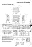
H V X PW T R oDB oDA GA GB F E Z L J K TA S TB G Q A A 2 C + Stroke B + Stroke A + Stroke W + Stroke 4 x NN through 2 x P 4 x YY depth YL 4 x MM depth ML 4 1.5 5.8 3.1 1.5 4 5.8 3.1 a a MGQL (Ball bushing bearing)/ A, DB, E Dimensions 32 40 50 63 80 100 A 50 st or less 53 54 60 61 84 89 Over 50 st 90 90 102 102 143 153 50 st or less 5.5 0 4 0 9.5 5 Over 50 st 42.5 36 46 41 68.5 69 DB E 16 16 20 20 25 30 (mm) Bore size (mm) Bore size (mm) 32 40 50 63 80 100 71.5 71.5 81 81 93 105 A DB 20 20 25 25 28 36 E 24 17.5 25 20 18.5 21 Grooves (Except o12, o16, o20, o25) Model MGQ尰32 MGQ尰40 MGQ尰50 MGQ尰63 MGQ尰80 MGQ尰100 A 8 8 8 8 10 10 Detailed figure of “a” section MGQ尰32 to 50 MGQ尰63 to 100 Detailed figure of “b” section MGQM, MGQL Common Dimensions Bore size (mm) 32 40 50 63 80 100 Standard stroke (mm) B 47.5 54 56 61 74.5 84 C 37.5 44 44 49 56.5 66 DA 16 16 20 20 25 30 F 8 8 10 10 16 16 G 51 51 59 72 92 112 GA 12.5 14 14 16.5 19 23 GB 9 10 11 13.5 15.5 19 H 114 124 140 150 188 224 J 25 25 29 35.5 45.5 55.5 K 26 26 30 36.5 46.5 56.5 L 38 38 44 44 56 62 MM M8 x 1.25 M8 x 1.25 M10 x 1.5 M10 x 1.5 M12 x 1.75 M14 x 2 ML 20 20 25 25 30 35 NN M8 x 1.25 M8 x 1.25 M10 x 1.5 M10 x 1.5 M12 x 1.75 M14 x 2 Rc1/8 Rc1/8 Rc1/4 Rc1/4 Rc3/8 Rc3/8 NPT1/8 NPT1/8 NPT1/4 NPT1/4 NPT3/8 NPT3/8 G1/8 G1/8 G1/4 G1/4 G3/8 G3/8 P PW 15 21 27 33 37 40 Q 30 30 40 50 60 80 R 96 106 120 130 160 190 S 48 48 56 69 88 108 25, 50, 75, 100 125,150 175, 200 Nil TN TF Bore size (mm) 32 40 50 63 80 100 T 112 122 138 148 185 221 TA 2 2 2 2 2.5 2.5 TB 1 1 1 1 1.5 1.5 V 80 90 100 110 140 170 W 5 10 10 10 15 15 X 100 110 124 132 166 200 YY M8 x 1.25 M8 x 1.25 M10 x 1.5 M10 x 1.5 M12 x 1.75 M14 x 2 YL 11 11 12.5 15 18 21 Z 16 17 17 19 21 25 Bore Size o32 to o100: MGQM, MGQL Note) For intermediate strokes other than standard strokes, refer to the Manufacture of Intermediate Stroke on page 435. 傱 Rc, NPT and G ports can be selected. (Refer to page 434.) Use grooves section “a” and section “b” in the figure below of the cylinder body for firmly fixing in the following case. (Applicable bolt size is M3.) . These grooves can be used for firmly fixing the tying bands of lead wires of the auto switch, etc., and also terminal boards, etc., to the main body of the cylinder. . When the terminal block is fixed on a cylinder directly. b b MGQM (Slide bearing)/ A, DB, E Dimensions 445 Compact Guide Cylinder Series MGQ MGJ MGP -Z MGP MGPW MGQ MGG MGC MGF MGZ MGT D-𡱖 -X𡱖