3-p0433-0449-mgq_en 15 / 18
10秒後にBOOKのページに移動します
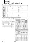
D-A9尰 D-A9尰V D-M9尰V D-M9尰 D-M9尰W D-M9尰A D-M9尰WV D-M9尰AV D-Z7尰 D-Z80 D-Y59尰 D-Y7P D-Y69尰 D-Y7PV D-Y7尰W D-Y7尰WV D-Y7BA Auto switch model No. of auto switches mounted 1 pc. 2 pcs. 1 pc. 2 pcs. 1 pc. 2 pcs. 1 pc. 2 pcs. 1 pc. 2 pcs. 1 pc. 2 pcs. 1 pc. 2 pcs. 1 pc. 2 pcs. 1 pc. 2 pcs. 5 Note 1) 10 Note 1) 5 Note 1) 5 Note 1) 10 Note 1) 10 5 10 10 Note 1) 10 Note 2) 10 10 5 5 (mm) o12 o16 o20 o25 o32 o40 o50 o63 o80 o100 A B Auto Switch Mounting Series MGQ Minimum Stroke for Auto Switch Auto Switch Proper Mounting Position (Detection at Sroke End) Note 1) Confirm that it is possible to secure the bending radius of 10 mm of the auto switch lead wire before use. Note 2) Confirm that it is possible to securely set the auto switch(es) within the range of indicator green light ON range before use. For in-line entry type, please also consider Note 1) shown above. Auto Switch Proper Mounting Position D-M9尰 D-M9尰V D-M9尰W D-M9尰WV D-M9尰A D-M9尰AV 12 16 20 25 32 40 50 63 80 100 A 6 9 9.5 9.5 10.5 14.5 12.5 15 18 22.5 B 8 9 12.5 13 12 14.5 16.5 19 23.5 28.5 D-A9尰 D-A9尰V A 2 5 5.5 5.5 6.5 10.5 8.5 11 14 18.5 B 4 5 8.5 9 8 10.5 12.5 15 19.5 24.5 D-Z7尰/Z80 D-Y59尰/Y7P D-Y69尰/Y7PV D-Y7尰W D-Y7尰WV D-Y7BA A 1 4 4.5 4.5 5.5 9.5 7.5 10 13 17.5 B 3 4 7.5 8 7 9.5 11.5 14 18.5 23.5 Auto Switch Mounting Height D-A9尰 D-M9尰 D-M9尰W D-M9尰A D-Z7尰 D-Z80 D-Y59尰 D-Y7P D-Y7尰W D-Y7BA 12 16 20 25 32 40 50 63 80 100 Hs 16 18.5 19.5 21 24.5 24 28 34.5 44 52 D-A9尰V Hs 18.5 21 22.5 23.5 27 26 30 36.5 46.5 54 D-M9尰V D-M9尰WV D-M9尰AV Hs 20.5 23 24.5 26 28.5 27.5 31.5 39.5 48.5 56 D-Y69尰 D-Y7PV D-Y7尰WV Hs 17 19.5 20.5 22 25.5 25 29 35.5 45 52.5 .Hs Auto switch Note) Adjust the auto switch after confirming the operating conditions in the actual setting. Auto switch model Auto switch model Bore size (mm) Bore size (mm) Note 2) Note 2) Note 2) Note 2) Note 2) Note 2) 5 10 5 5 10 5 10 5 5 5 10 (mm) (mm) 446