3-p0433-0449-mgq_en 4 / 18
10秒後にBOOKのページに移動します
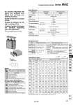
Symbol Rubberbumper -XA -XB6 -XB9 -XB10 -XC22 -XC56 -XC79 Change of rod end shape Heat resistant cylinder (.10 to 150°C) Low speed cylinder (10 to 50 mm/s) Intermediate stroke (Using exclusive body) Fluororubber seals With knock pin holes Machining tapped hole, drilled hole, and pin hole additionally Symbol Specifications -X168 -X367 -X399 -X563 Helical insert thread Bottom mounting style Long bushing type With anti-strong magnetic field switch (D-P4DW) Symbol Specifications 12, 16, 20, 25, 32, 40, 50, 63, 80, 100 Specifications Double acting Air 1.5 MPa 1.0 MPa 0.12 MPa 0.1 MPa .10 to 60°C (No freezing) 50 to 500 mm/s 50 to 400 mm/s Rubber bumper on both ends Non-lube mm o12, o16 o20 to o100 o12 to o63 o80, o100 Standard Stroke Model Standard stroke (mm) 10, 20, 30, 40, 50, 75, 100 20, 30, 40, 50, 75, 100 125, 150, 175, 200 25, 50, 75, 100, 125 150, 175, 200 Intermediate stroke (mm) MGQ 12, 16 ML ML ML MGQ 20, 25 MGQ 32, 40 50, 63 80, 100 Theoretical Output (N) Bore size (mm) 12 16 20 25 32 40 50 63 80 100 Rod size (mm) Operating direction 6 8 10 12 16 16 20 20 25 30 0UT IN 0UT IN 0UT IN 0UT IN 0UT IN 0UT IN 0UT IN 0UT IN 0UT IN 0UT IN Piston area (mm2) 113 85 201 151 314 236 491 378 804 603 1257 1056 1963 1649 3117 2803 5027 4536 7854 7147 0.2 23 17 40 30 63 47 98 76 161 121 251 211 393 330 623 561 1005 907 1571 1429 0.3 34 26 60 45 94 71 147 113 241 181 377 317 589 495 935 841 1508 1361 2356 2144 0.4 45 34 80 60 126 94 196 151 322 241 503 422 785 660 1247 1121 2011 1814 3142 2859 0.5 57 43 101 76 157 118 246 189 402 302 629 528 982 825 1559 1402 2514 2268 3927 3574 0.6 68 51 121 91 188 142 295 227 482 362 754 634 1178 990 1870 1682 3016 2722 4712 4288 0.7 79 60 141 106 220 165 344 265 563 422 880 739 1374 1154 2182 1962 3519 3175 5498 5003 0.8 90 68 161 121 251 189 393 302 643 482 1006 845 1570 1319 2494 2242 4022 3629 6283 5718 0.9 102 77 181 136 283 212 442 340 724 543 1131 950 1767 1484 2805 2523 4524 4082 7069 6432 1.0 113 85 201 151 314 236 491 378 804 603 1257 1056 1963 1649 3117 2803 5027 4536 7854 7147 Operating pressure (MPa) Note) Theoretical output (N) = Pressure (MPa) x Piston area (mm2) OUT(N) IN(N) Slide bearing MGQM Ball bushing bearing MGQL +1.5 0 Bearing type Model Air cylinder integrated with guide has achieved antilateral load and high nonrotating accuracy. Space-saving and compact design Suitable as stoppers or lifters in conveyor line 2 types of guide rod bearing are available depending upon the application Slide bearing/Ball bushing bearing Bore size (mm) Action Fluid Proof pressure Max. operating pressure Min. operating pressure Cushion Lubrication Stroke length tolerance Ambient and fluid temperature Piston speed As for the intermediate strokes other than the standard strokes at left are manufactured by means of installing a spacer. o12 to o32 ・・・・・・ Stroke available by the 1 stroke interval o40 to o100 ・・・・ Stroke available by the 5 stroke interval (Example) 1. For MGQM20-21 st, MGQM20-30 st is provided with a 5 mm + 4 mm . 9 mm width spacer. 2. For MGQM50-40 st, MGQM50-50 st is provided with a 10 mm width spacer. Made to Order Specifications (For details, refer to pages 2009 to 2152.) Made to Order: Individual Specifications (For details, refer to pages 448 and 449.) 435 Compact Guide Cylinder Series MGQ MGJ MGP -Z MGP MGPW MGQ MGG MGC MGF MGZ MGT D- -X