3-p0433-0449-mgq_en 6 / 18
10秒後にBOOKのページに移動します
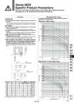
o100 o80 o63 o32 o25 o16 o12 o20 o50 o40 o100 o80 o63 o32 o25 o16 o12 o20 o50 o40 A±0.2 B±0.2 C±0.2 A±0.2 B±0.2 2d or more (d = Thread O.D.) Max. speed (mm/s) Load mass (kg) 100 1000 100 10 0.1 0.01 Max. speed (mm/s) Load mass (kg) 100 200 300 400 500 200 300 400 500 1000 100 10 1 1 0.1 0.01 oD By-pass port dia. oD By-pass port dia. Allowable Kinetic Energy MGQ without a cushion (XB6, XC22) MGQ with a rubber bumper 12 16 20 25 32 40 50 63 80 100 40 42 52 62 80 90 100 110 140 170 18 22 26 32 38 38 44 44 56 62 36 38 46 56 . . . . . . MGQM 10 12 14 18 22 22 27 27 31 39 oD(mm) MGQL 8 10 12 15 18 18 22 22 28 33 M4 x 0.7 M5 x 0.8 M5 x 0.8 M6 x 1 M8 x 1.25 M8 x 1.25 M10 x 1.5 M10 x 1.5 M12 x 1.75 M14 x 2 Bore size (mm) A (mm) B (mm) C (mm) Hexagon socket head cap screw C dimension for a bore size of 32 to 100 is identical to the A dimension. Mounting Warning Caution Series MGQ Specific Product Precautions Be sure to read before handling. Refer to front matter 39 for Safety Instructions and pages 3 to 12 for Actuator and Auto Switch Precautions. 1.Avoid placing your hands or fingers between the plate and the body. . Be very careful to prevent your hands or fingers from getting caught in the gap between the cylinder body and the plate when air is applied. 1. Do not scratch or gouge the sliding portion of the piston rod and the guide rod. . Damaged seals, etc. will result in leakage or malfunction. 2. Do not dent or scratch the mounting surface of a body and a plate. . The flatness of the mounting surface may not be maintained, which would cause the sliding resistance to increase. 3.Make sure that the cylinder mounting surface has a flatness of 0.05 mm or less. . If the flatness of the workpieces and brackets mounted on the plate is not appropriate, sliding resistance may increase. 4. When mounting on the bottom of the cylinder, the guide rod protrudes from the bottom at the retraction stroke end. Therefore, drill holes for the hexagon socket bolts used for mounting purposes, and relief holes for the guide rods. Moreover, in applications where impact occurs from a stopper, etc., the mounting bolts should be inserted to a depth of 2 d or more. Load mass and cylinder speed should be observed within the range given in the graph below. 437 MGJ MGP -Z MGP MGPW MGQ MGG MGC MGF MGZ MGT D-𡱖 -X𡱖