3-p0523-0550-mgzmgzr_en 28 / 29
10秒後にBOOKのページに移動します
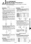
L1 L2 Series MGZ/MGZR Specific Product Precautions 1 Be sure to read before handling. Refer to front matter 39 for Safety Instructions and pages 3 to 12 for Actuator and Auto Switch Precautions. Model Bolt Proper tightening torque N.m L1 MGZ/MGZR20 MGZ/MGZR25 MGZ/MGZR32 MGZ/MGZR40 MGZ/MGZR50 MGZ/MGZR63 MGZ/MGZR80 M5 x 0.8 M5 x 0.8 M6 x 1 M6 x 1 M8 x 1.25 M8 x 1.25 M12 x 1.75 2.5 to 3.1 2.5 to 3.1 4.1 to 6.4 4.1 to 6.4 8.8 to 13.8 8.8 to 13.8 30.4 to 47.5 10 10 12 12 15 15 23 L2 11 11 16 16 16 16 20 Model Applicable floating joint MGZR20 MGZR25 MGZR32 MGZR40 MGZR50 MGZR63 MGZR80 JB40-8-125 JB63-10-150 JB80-16-200 JB100-20-250 JB140-22-250 1. Do not apply more than the allowable rotating torque to the piston rod (for Series MGZ: with nonrotating mechanism). If more than the allowable rotating torque is applied, the slide keys for non-rotation will be deformed and non-rotating accuracy will be lost. This may cause damage to machinery. Selection 1. Operate load within the range of the operating limits. In accordance with the model selection procedure, operate within the operating limits of load weight, maximum speed, center of gravity position and allowable rotating torque. Operation beyond the operating limits can cause wear of the bearings and loosening of connections, leading to damage of machinery. 2. Compared to regular cylinders, at least twice the time is required for movement to begin in the retracting direction. Cylinders featured in this catalog are filled with twice the amount of air at the extending compared to regular cylinders, therefore a longer time is required to exhaust the air before movement in the retracting direction begins. 3. Construct equipment so that reactive forces such as external stoppers and pressing are applied to the cylinder's central axis. Design the external stopper or die so that when a cylinder stops before the stroke end on a stopper or press, the reactive force is applied to the cylinder's central axis. Off-center operation can cause wear of the bearings and loosening connections, leading to damage of machinery. 4. Under horizontal or downward operating conditions, lurch prevention measures may be required for the cylinder's extending operation. Since the output force of the cylinders featured in this catalog in the extending direction is at least double that in the retracting direction, start-up operation for extension may exceed the control speed of the speed controller. In this case, provide a lurch prevention circuit within the pneumatic circuitry. 5. Do not over throttle the meter-in speed controller of the lurch prevention circuit. Throttling the meter-in speed controller will make the start-up time for output in the extending direction longer. Operation Caution Caution Correct Incorrect 1. When mounting the cylinder, use mounting bolts of a suitable length, and tighten them properly within the specified range of tightening torque. Particularly in case of frequent operation or much vibration, emply measures to prevent loosening of the bolts, such as the application of a thread locker. Mounting Caution 2. Do not gouge or scratch the mounting surfaces of the rod cover and head cover. Evenness of mounting surfaces will be degraded, causing increased operating resistance and wear of the bearings etc. 3. Mounting of workpiece on the rod end When screwing bolts into the threads of the table surface at the end of the piston rod, be sure the piston rod is fully retracted and use the wrench flats to hold the rod. Tighten the bolts in such a way that the tightening torque is not applied to the non-rotation slide keys. (for Series MGZ: with non-rotating mechanism). 4. Allowable angle displacement of 尰E to 尰B is 𡵸1.5°. (for Series MGZ: with non-rotating mechanism) 1. When using a floating joint at the end of the tube rod, use the model specified in the table below. (for Series MGZR: without non-rotating mechanism) Applicable Floating Joint Caution 尰E 尰B 549 MGJ MGP -Z MGP MGPW MGQ MGG MGC MGF MGT D-𡱖 -X𡱖 MGZ