3-p0523-0550-mgzmgzr_en 7 / 29
10秒後にBOOKのページに移動します
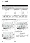
o63 o80 o50 o40 o32 o25 o20 o63 o80 o50 o40 o32 o25 o20 o80 o63 o50 o40 o32 o25 o20 Series MGZR 600 500 400 300 200 100 0 0.1 0.2 0.3 0.4 0.5 0.6 0.7 0.8 0.9 1 Operating pressure P (MPa) Load mass m (kg) 500 400 300 200 100 0 0.1 0.2 0.3 0.4 0.5 0.6 0.7 0.8 0.9 1 Operating pressure P (MPa) Load mass m (kg) 300 250 200 150 100 50 0 Operating pressure P (MPa) Load mass m (kg) 0.1 0.2 0.3 0.4 0.5 0.6 0.7 0.8 0.9 1 1. Find the Bore Size of the Cylinder Tube Selection Graph (1) to (3) (Vertical Upward Load) Graph (1) up to 300 mm/s Graph (2) up to 500 mm/s Selection conditions: Determine which of the conditions below matches your intended application, then choose one of the selection graphs that follow. Series MGZR (without non-rotating mechanism) Vertical upward load Maximum speed (mm/s) Up to 300 Graph (1) Up to 500 Graph (2) Up to 700 Graph (3) Up to 300 Graph (4) Up to 500 Graph (5) Up to 700 Graph (6) Up to 300 Graph (7) Up to 450 Graph (8) Maximum speed (mm/s) Maximum speed (mm/s) Load extended horizontally Load retracted horizontally m m m Graph (3) up to 700 mm/s Selection Example: Vertical Upward Load Solid line: Operating pressure 0.4 MPa or more q Selection conditions Mounting: Vertical upward Maximum speed: 500 mm/s Operating pressure: 0.8 MPa Load mass: 150 kg Since the conditions are vertical upward mounting with a speed of 500 mm/s, use graph (2). In the graph, find where the lines representing an operating pressure of 0.8 MPa and a load mass of 150 kg intersect. A o50 bore size is selected. 528