3-p0625-0638-cxt_en 3 / 15
10秒後にBOOKのページに移動します
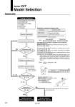
Bearing type . Impact load and vibration load are added. . Change in load is large. . Long life span is required. . High accuracy (Little rattle is allowed.) . Smooth operation Slide bearing Ball bushing bearing Required conditions Guideline for Selection of Bearing Type Determine the movable weight WA which can be operated only by adjusting bolts. W θ θ Bore size Distance between guide rods GP 40 130 32 110 25 90 20 80 16 65 12 50 W GP L (mm) Setting Conditions Confirmation of sum of load ratio to the guide unit Σαn . 1 Selection of bearing type Model selected Without shock absorber NO Series CXT Model Selection Selection Step Provisional selection of cylinder bore size Calculation of resistance force f Calculation of theoretical output F Calculation of load ratio β to the theoretical output of cylinder β = f / F Confirmation of adjusting bolt capacity W . WA Model selected With shock absorber YES YES NO β > 0.5 β . 0.5 Σαn = ............. + ........... Load weight [W] Maximum load weight [Wmax] Moment [mn] Allowable moment [Mn] Horizontal mounting: f = μ x W Inclined mounting: f = μ x Wcosθ + Wsinθ (Refer to the figure on the right.) Vertical mounting: f = W μ = 0.3 (Slide bearing) μ = 0.1 (Ball bushing bearing) Σαn . .... 1 (L/GP) 2 (Provided that L > GP) 1. Mounting (Horizontal, Inclined, Vertical) 2. Load weight W (kg) 3. Operating pressure P (MPa) P . 0.7 MPa 4. Speed V (mm/s) V . 500 mm/s Refer to “Theoretical Output” on page 629. The moment load rate must be calculated in accordance with the above formula for all types, M1 to M3. As for Wmax and Mn, refer to the maximum load weight and allowable moment table in the next section. The moment for the inclined mounting must be calculated taking the moment caused by the load into consideration. Note) Make sure that the distance between the guide shaft center to the center of gravity of the load does not exceed the distance GP between the guide shafts given in the table below. If the distance must be exceeded due to unavoidable circumstances, decrease the load rate that is applied to the guide as indicated below in order to determine the distance. Load weight [W] are as follows in compliance to the mounting way. Horizontal mounting: W Inclined mounting: Wcosθ (θ: Angle of inclination, refer to the figure below.) Vertical mounting: 0 (None) 626