3-p0625-0638-cxt_enЃ@Ѓ@Ѓ@4 / 15
10•bЊг‚ЙBOOK‚МѓyЃ[ѓW‚Й€Ъ“®‚µ‚Ь‚·
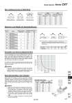
M1 M3 L M2 L Bore size (mm) Bearing Maximum load weight Wmax (kg) Allowable moment (N ЃE m) M1 (= M3) M2 1.25 0.53 3.34 1.53 11.4 5.60 11.4 5.60 19.8 10.1 37.3 21.3 1.68 0.70 4.25 2.11 17.1 7.28 19.3 8.19 23.3 14.8 46.2 27.5 Slide bearing Ball bushing bearing Slide bearing Ball bushing bearing Slide bearing Ball bushing bearing Slide bearing Ball bushing bearing Slide bearing Ball bushing bearing Slide bearing Ball bushing bearing 12 16 20 25 32 40 3 7 12 20 30 50 Bore size L dimension 12 19.5 16 24 20 28 25 31 32 39.5 40 47.5 Allowable Static Mass Bore size (mm) 12 16 20 25 32 40 CXTM CXTL 350 500 900 900 1100 1900 60 70 125 125 140 170 50 45 40 35 30 25 20 15 10 5 0 100 200 300 400 500 Speed (mm/s) Load weight (kg) (Slide bearing) (Ball bushing bearing) (kg) ѓЖr Pitching direction Rolling direction Yawing direction Bore size (mm) 12 16 20 25 32 40 CXTM CXTL (Slide bearing) (Ball bushing bearing) ѓЖp (= ѓЖy) ѓЖr ѓЖp (= ѓЖy) ѓЖr Ѓ} 0.09Ѓ‹ Ѓ} 0.08Ѓ‹ Ѓ} 0.07Ѓ‹ Ѓ} 0.07Ѓ‹ Ѓ} 0.08Ѓ‹ Ѓ} 0.06Ѓ‹ Ѓ} 0.12Ѓ‹ Ѓ} 0.10Ѓ‹ Ѓ} 0.08Ѓ‹ Ѓ} 0.07Ѓ‹ Ѓ} 0.07Ѓ‹ Ѓ} 0.06Ѓ‹ Ѓ} 0.05Ѓ‹ Ѓ} 0.05Ѓ‹ Ѓ} 0.04Ѓ‹ Ѓ} 0.04Ѓ‹ Ѓ} 0.04Ѓ‹ Ѓ} 0.03Ѓ‹ Ѓ} 0.05Ѓ‹ Ѓ} 0.04Ѓ‹ Ѓ} 0.03Ѓ‹ Ѓ} 0.03Ѓ‹ Ѓ} 0.03Ѓ‹ Ѓ} 0.03Ѓ‹ ѓЖp ѓЖy (mm) Maximum Load Weight and Allowable Moment Static Movable Mass when Stopped Allowable Load Only by Adjustment Bolt If only the adjustment bolt is used for stopping the load, make sure that the load weight and the speed will be below the curve in the graph on the right, taking into consideration the durability of the rubber bumper that is attached to the end of the adjustment bolt and the vibration and noise that are created when stopping (provided that the maximum load weight is not exceeded). In conditions in which the load weight and the speed will be above the curve, use a shock absorber (provided that the maximum load weight not exceeded). In the case of the ball bushing type, the service life could be drastically shortened if shocks or excessive moments are applied. Therefore, even if the conditions given above are not exceeded, the use of a shock absorber is recommended. Non-rotating Accuracy of Slide Block Caution When Series CXT cylinder is used for moving the workpiece receptacle, such as in a stamping or press-fitting process, a vertical load will be applied to the top surface of the stopped slide block (refer to the figure on the right). In this case, the allowable mass is greater than the maximum load weight, as given in the table on the right. 1. Make sure that the slide block is stopped at the stroke end. 2. Match the center of the mass to be applied with the center of the slide block. The direction of the mass must be vertically downward in relation to the surface on which the workpiece is mounted, as shown in the figure on the right. 3. Do not apply a load that involves shocks such as those caused by pounding (particularly with the ball bushing style). 4. If this mass is applied, the deflection of the guide shaft will also have a large value. Caution Note) For the purpose of calculating the moment, the length of the arm is the distance that is measured from the guide shaft center (Ѓgр‘Ѓh mark). Dimension L from the guide shaft center to the top surface of the table is indicated below. Model Selection Series CXT 627 CX2 CXW CXSJ CXS D-р® -Xр® CXT