3-p0701-0768-cl_en 10 / 69
10秒後にBOOKのページに移動します
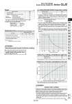
Weight (g) Bore size (mm) Standard weight . Additional weight per each 15 mm of stroke Mounting bracket Weight Axial foot style Rod side flange style Double clevis style (With pin) .. 16 320 6.5 27 21 10 . Mounting nut and rod end nut are included in the basic weight. .. Mounting nut is not included in double clevis style. Calculation: (Example) CLJ2L16-60 . Basic weight・・・・・・・・・・・・・・・・・320 (o16) . Additional weight・・・・・・・・・・6.5/15 stroke . Cylinder stroke・・・・・・・・・・・・・60 stroke 320 + 6.5/15 x 60 + 27 = 373 g . When selecting cylinders, refer to the Precautions and allowable kinetic energy when locking on page 702, and then select a cylinder. Stopping Accuracy (Not including tolerance of control system.) (mm) Lock type Spring locking (Exhaust locking) Pneumatic locking (Pressure locking) Spring and pneumatic locking Piston speed (mm/s) 50 ± 0.4 ± 0.2 100 ± 0.5 ± 0.3 300 ± 1.0 ± 0.5 500 ± 2.0 ± 1.5 Caution/Allowable Kinetic Energy when Locking Bore size (mm) Allowable kinetic energy (J) 16 0.17 Holding Force of Spring Locking (Maximum static load) Bore size (mm) Holding force (N) 16 122 Condition: Load: 2 kg Solenoid valve: Lock port mounting Note) Holding force at piston rod extended side decreases approximately 15%. 0 50 100 200 300 400 500 1 2 3 4 4.4 5 6 7 8 9 Load mass (kg) Piston speed (mm/s) 0 50 100 150 200 0.1 0.2 0.3 0.4 0.5 Air pressure applied to pressurized locking port (MPa) Holding force (N) Holding Force of Pneumatic Locking (Maximum static load) For detailed specifications of the fine lock cylinder, Series CLJ2 mentioned above, refer to pages 702 to 705. Selection/Recommended Pneumatic Circuit/Caution on Handling Caution Caution when Locking Holding force (maximum static load) means the maximum capability of holding a static load that is not accompanied by vibration or impact under the condition that no load is applied. Therefore, it does not refer to a load that cannot be held constantly. When using (selecting) this product, carefully check the following points. . If the piston rod slips because the lock’s holding force has been exceeded, the brake shoe could be damaged, resulting in a reduced holding force or shortened life. . The upper limit of the load that is used under the conditions not associated with the kinetic energy when locking, such as drop prevention must be 35% or less of the holding force. . Do not use the cylinder in the locked state to sustain a load that involves impact. Caution 1. In terms of specific load conditions, this allowable kinetic energy is equivalent to a load of 3.7 kg in mass, and a piston speed of 300 mm/sec. Therefore, if the operating conditions are below these values, there is no need to calculate. 2. Apply the following formula to obtain the kinetic energy of the load. Ek: Kinetic energy of load (J) m: Load mass (kg) υ: Piston speed (m/s) 3. The piston speed will exceed the average speed immediately before locking. To determine the piston speed for the purpose of obtaining the kinetic energy of load, use 1.2 times the average speed as a guide. 4. The relationship between the speed and the load is indicated in the graph below. The area below the line is the allowable kinetic energy range. 5. There is an upper limit to the size of the load that can be sustained. Thus, a horizontally mounted cylinder must be operated below the solid line, and a vertically mounted cylinder must be operated below the dotted line. 1 2 Ek = . mυ2 Series CLJ2 Fine Lock Cylinder Double Acting, Single Rod 709 CLJ2 CLM2 CLG1 CL1 MLGC CNG MNB CNA2 CNS CLS CLQ RLQ MLU MLGP ML1C D- -X