3-p0701-0768-cl_en 20 / 69
10秒後にBOOKのページに移動します
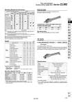
Series CLM2 Fine Lock Cylinder Double Acting, Single Rod o20 o25 o32 o40 (mm) 0.55 0.70 0.61 0.53 0.59 0.60 0.59 0.54 0.60 0.04 0.07 0.06 0.07 0.06 0.02 20 0.87 1.03 0.96 0.85 0.91 0.93 0.94 0.85 0.94 0.06 0.07 0.06 0.07 0.06 0.02 25 0.94 1.10 1.03 0.93 0.98 0.99 1.00 0.92 1.01 0.08 0.14 0.06 0.07 0.06 0.02 32 1.30 1.57 1.42 1.26 1.39 1.43 1.40 1.27 1.39 0.13 0.14 0.23 0.20 0.06 0.03 40 (kg) CLM2H 20 25 32 40 CM-L020B CM-F020B CM-C020B CM-D020B CM-T020B CM-L032B CM-F032B CM-C032B CM-D032B CM-T032B CM-L040B CM-F040B CM-C040B CM-D040B CM-T040B Mounting Bracket and Accessory Note 1) Mounting nut is not equipped with clevis integrated style, single clevis style and double clevis style. Note 2) Trunnion nuts are attached for head side trunnion style. Note 3) Pin and retaining ring (o40: cotter pin) are shipped together with double clevis and double knuckle joint. Note 4) Pin and retaining ring are shipped together with clevis pivot bracket. Note 5) Clevis pins come with retaining rings (cotter pins for o40). Note 6) Pivot brackets do not come with pins and retaining rings. Note 7) Pivot bracket pins come with retaining rings. Basic style Axial foot style Rod side flange style Head side flange style Clevis integrated style Single clevis style Double clevis style(3) Head side trunnion style Boss-cut basic style Boss-cut flange style Note With pin With pin Accessory Standard equipment Option Mounting nut Rod end nut Single knuckle joint Double(3) knuckle joint Clevis pin Clevis(4) pivot bracket Pivot(6) bracket Pivot(7) bracket pin Rod Mounting boot Weight Bore size (mm) Basic weight Option bracket Basic style Axial foot style Flange style Clevis integrated style Single clevis style Double clevis style Trunnion style Boss-cut basic style Boss-cut flange style Clevis bracket (With pin) Single knuckle joint Double knuckle joint (With pin) Pivot bracket Pivot bracket pin Additional weight per each 50 mm of stroke Calculation: (Example) CLM2L32-100-E . Basic weight ・・・・・・・・・・・・・ 1.10 (Foot, o32) . Additional weight ・・・・・・ 0.08/50 stroke . Cylinder stroke ・・・・・・・ 100 stroke 1.10 + 0.08 x 100/50 = 1.26 kg Mounting Bracket Part No. Bore size (mm) Axial foot . Flange Single clevis Double clevis .. Trunnion (with nut) Boss-cut style Boss for the head side cover bracket is eliminated and the total length of cylinder is shortened. Comparison of the full length dimension (Versus standard type) Mounting style 傖 Boss-cut basic style (BZ) 傖 Boss-cut flange style (FZ) Air-hydro Mounting style Bore size Stroke Rod boot Air-hydro Low hydraulic cylinder 1 MPa or less Through the concurrent use of a CC series air-hydro unit, it is possible to operate at a constant or low speeds or to effect an intermediate stop, just like a hydraulic unit, while using pneumatic equipment such as a valve. Fluid Action Bore size (mm) Maximum operating pressure Minimum operating pressure Piston speed Cushion Piping Basic style, Axial foot style, Rod side flange style Head side flange style, Single clevis style Double clevis style, Head side trunnion style Clevis integrated style, Boss-cut style Turbine oil (Lock portion is air) Double acting, Single rod o20, o25, o32, o40 1.0 MPa 0.2 MPa 15 to 300 mm/s Rubber bumper (Standard equipment) Screw-in type Mounting Specifications . Auto switch capable . For an exterior dimension diagram to identify the mounting support types, refer to pages 722 to 726 as the dimensions are identical to those of standard. . When ordering foot bracket, order 2 pieces per cylinder. .. Clevis pin and retaining ring (o40: cotter pin) are shipped together with double clevis style. 719 CLJ2 CLM2 CLG1 CL1 MLGC CNG MNB CNA2 CNS CLS CLQ RLQ MLU MLGP ML1C D-𡱖 -X𡱖