3-p0701-0768-cl_en 21 / 69
10秒後にBOOKのページに移動します
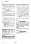
20 . ±0.3 ±0.15 50 ±0.4 ±0.2 100 ±0.5 ±0.3 300 ±1.0 ±0.5 500 ±2.0 ±1.5 Stopping Accuracy (Not including tolerance of control system.) (mm) Spring locking (Exhaust locking) Pneumatic locking (Pressure locking) Spring and pneumatic locking Locking method Piston speed (mm/s) Conditions: Load: 25% of thrust force at 0.5 MPa Solenoid valve: Mounted to the lock port 20 mm/s marked with the asterisk is in the case of actuating hydraulically by means of air-hydro type. Caution Selection/Recommended Pneumatic Circuit/Caution on Handling For detailed speceifications of the fine lock cylinder, Series CLM2 mentioned above, refer to pages 702 to 705. o40 o40 o32 o25 o20 o32 o25 o20 o40 o32 o25 o20 Series CLM2 20 25 32 40 0.26 0.42 0.67 1.19 Bore size (mm) Allowable kinetic energy (J) Caution/Allowable Kinetic Energy when Locking 1. In terms of specific load conditions, the allowable kinetic energy indicated in the table above is equivalent to a 50% load ratio at 0.5 MPa, and a p i ston speed o f 300 mm/ sec . Therefore, i f the operating conditions are below these values, calculations are unnecessary. 2. Apply the following formula to obtain the kinetic energy of the load. 3. The piston speed will exceed the average speed immediately before locking. To determine the piston speed for the purpose of obtaining the kinetic energy of load, use 1.2 times the average speed as a guide. 4. The relation between the speed and the load of the respective tube bores is indicated in the diagram below. Use the cylinder in the range below the line. 5. Even within a given allowable kinetic energy level, there is an upper limit to the size of the load that can be sustained. Thus, a horizontally mounted cylinder must be operated below the solid line, and a vertically mounted cylinder must be operated below the dotted line. Ek: Kinetic energy of load (J) m: Load mass (kg) υ: Piston speed (m/s) 1 2 0 50 100 200 300 400 500 20 10 30 40 50 60 Load mass (kg) Piston speed (mm/s) 40 784 32 443 25 313 20 196 Bore size (mm) Note) Holding force at piston rod extended side decreases approximately 15%. Holding Force of Spring Locking (Maximum static load) Holding force (N) Holding Force of Spring Locking (Maximum static load) 0 500 1000 0.1 0.2 0.3 0.4 0.5 . When selecting cylinders, refer to the Precautions and allowable kinetic energy when locking on page 702, and then select a cylinder. Air pressure applied to pressurized locking port (MPa) Holding force (N) Bore size Caution Caution when Locking Holding force (maximum static load) means the maximum capability of holding a static load that is not accompanied by vibration or impact under the condition that no load is applied. Therefore, it does not refer to a load that cannot be held constantly. When using (selecting) this product, carefully check the following points. . If the piston rod slips because the lock’s holding force has been exceeded, the brake shoe could be damaged, resulting in a reduced holding force or shortened life. . Do not use the cylinder in the locked state to sustain a load that involves impact. . The upper limit of the load that is used under the conditions not associated with the kinetic energy when locking, such as drop prevention must be 35% or less of the holding force. Caution Operating Precautions . Install a rod boot without twisting. If the cylinder is installed with its bellows twisted, it could damage the bellows. 720