3-p0701-0768-cl_en丂丂丂35 / 69
10昩屻偵BOOK偺儁乕僕偵堏摦偟傑偡
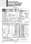
. 100 V 100 V or less 100 V, 200 V 200 V or less . 24 V or less . . 24 V Perpendicular In-line 24 V 5 V, 12 V 12 V 5 V, 12 V 12 V 5 V, 12 V 12 V 5 V, 12 V 5 V 12 V . 饤 饤 饤 饤 饤 饤 饤 饤 饤 饤 饤 饤 饤 鸱 鸱 鸱 饤 饤 饤 饤 饤 饤 饤 饤 饤 饤 饤 饤 饤 饤 饤 饤 饤 饤 饤 饤 饤 饤 饤 饤 饤 饤 饤 饤 饤 饤 饤 饤 饤 饤 饤 饤 饤 . 饤 . 饤 . . 饤 . 饤 . 饤 . 鸱 鸱 鸱 . . . 饤 . . . . . . 鸱 鸱 鸱 鸱 鸱 鸱 饤 鸱 鸱 鸱 鸱 鸱 鸱 鸱 鸱 鸱 鸱 鸱 . 饤 . 饤 . 饤 饤 . . . . . . . 饤 . . . . . . . . . . . . . . . . 饤 饤 . 鸱 鸱 鸱 鸱 鸱 鸱 . 鸱 鸱 鸱 鸱 鸱 鸱 鸱 鸱 鸱 鸱 鸱 . . . . . . . . M9N . M9P . M9B . H7C M9NW . M9PW . M9BW . M9NA.1 M9PA.1 M9BA.1 . H7NF A96 A93 A90 B54 B64 C73C C80C B59W M9NV . M9PV . M9BV . . M9NWV . M9PWV . M9BWV . M9NAV.1 M9PAV.1 M9BAV.1 . . A96V A93V.2 A90V . . . . . . C Nil J K Without rod boot Nylon tarpaulin Heat resistant tarpaulin 20 25 32 40 20 mm 25 mm 32 mm 40 mm Bore size CLG1 CDLG1 L N 25 100 E With auto switch L N 25 100 E M9BW B L F G U T D How to Order Mounting style Basic style Axial foot style Rod side flange style Head side flange style Rod side trunnion style Head side trunnion style Clevis style DC AC 3 (L) 1 (M) 5 (Z) . . . . . . . Applicable Auto Switches/Refer to pages 1893 to 2007 for further information on auto switches. Type Reed auto switch Solid state auto switch Electrical entry Indicator light Wiring (Output) Load voltage Auto switch model Applicable bore size Lead wire length (m) Applicable load Pre-wired connector Diagnostic indication (2-color indication) Diagnostic indication (2-color indication) Water resistant (2-color indication) With diagnostic output (2-color indication) Grommet Grommet Grommet Grommet Connector Connector Yes No Yes No Yes No Yes Yes 3-wire (NPN) 3-wire (NPN) 3-wire (NPN) 3-wire (PNP) 3-wire (PNP) 3-wire (PNP) 2-wire 2-wire 2-wire 2-wire 4-wire (NPN) 3-wire (NPN equivalent) 0.5 (Nil) None (N) IC circuit IC circuit IC circuit IC circuit IC circuit IC circuit IC circuit Relay, PLC Relay, PLC .1 Water resistant type auto switches can be mounted on the above models, but in such case SMC cannot guarantee the water resistance. A water-resistant type cylinder is recommended for use in an environment which requires water resistance. However, please contact SMC for water-resistant products of o20 and o25. .2 1 m type lead wire is only applicable to D-A93. . Lead wire length symbols: 0.5 m 丒丒丒丒丒丒丒Nil (Example) M9NW 1 m 丒丒丒丒丒丒丒M (Example) M9NWM 3 m 丒丒丒丒丒丒丒 L (Example) M9NWL 5 m 丒丒丒丒丒丒丒 Z (Example) M9NWZ None 丒丒丒丒丒丒丒 N (Example) H7CN . Solid state auto switches marked with 乬 乭 are produced upon receipt of order. . Since there are other applicable auto switches than listed above, refer to page 745 for details. . For details about auto switches with pre-wired connector, refer to pages 1960 and 1961. . D-A9瓠(V)/M9瓠(V)/M9瓠W(V)/M9瓠A(V) auto switches are shipped together (not assembled). (Only auto switch mounting brackets are assembled at the time of shipment.) With auto switch (Built-in magnet) . Mounting bracket is shipped together, (but not assembled). Built-in Magnet Cylinder Model If a built-in magnet cylinder without an auto switch is required, there is no need to enter the symbol for the auto switch. (Example) CDLG1FA32-100-P N A Type Non-lube/Rubber bumper Non-lube/Air cushion Nil TN Rc NPT Port thread type 20 25 32 40 201 to 350 301 to 400 301 to 450 301 to 800 25, 50, 75, 100, 125, 150, 200 25, 50, 75, 100, 125, 150, 200, 250, 300 Cylinder stroke (mm) Bore size (mm) Standard stroke (mm) Long stroke (mm) . Intermediate stroke is available, too. E P D Spring locking (Exhaust locking) Pneumatic locking (Pressure locking) Spring and pneumatic locking Lock operation Cylinder symbol Nil Without auto switch . For the applicable auto switch model, refer to the table below. Nil S n 2 pcs. 1 pc. 乬n乭 pcs. Number of auto switches Auto switch Made to Order Refer to page 735 for details. Auto switch mounting bracket Note) Note) This symbol is indicated when the DA9 瓠 or M9瓠 type auto switch is specified. This mounting bracket does not apply to other auto switches (D-C7瓠 and H7瓠, etc.) (Nil) Special function . 734 Fine Lock Cylinder Double Acting, Single Rod Series CLG1 o20, o25, o32, o40 A