3-p0701-0768-cl_en 36 / 69
10秒後にBOOKのページに移動します
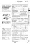
20 25 32 40 Air Not required (Non-lube) 1.5 MPa 1 MPa 0.08 MPa 20 25 32 40 25, 50, 75, 100, 125, 150, 200 25, 50, 75, 100, 125, 150, 200, 250, 300 201 to 350 301 to 400 1500 301 to 450 301 to 800 -XA (kg) . Intermediate stroke is available, too. Spacers are not used. . Long strokes are applicable for the axial foot and rod side flange styles. If other mounting brackets are used or the length exceeds the long stroke limit, the maximum stroke should be determined based on the stroke selection table (technical data). . Pin and retaining ring are shipped together with double knuckle joint. CLG1N CLG1A 20, 25 32, 40 Refer to the minimum auto switch mounting stroke (page 743) for those with an auto switch. Locking in both directions The piston rod can be locked in either direction of its cylinder stroke. Maximum piston speed: 500 mm/s It can be used at 50 to 500 mm/s provided that it is within the allowable kinetic energy range. Provided with a compact lock mechanism, it is suitable for intermediate stop, emergency stop, and drop prevention. Change of rod end shape Symbol Specifications Weight Bore size (mm) Basic style Axial foot style Flange style Trunnion style Clevis style Basic weight Rod side pivot bracket Head side pivot bracket Single knuckle joint Double knuckle joint (with pin) Additional weight per each 50 mm of stroke Additional weight with air cushion Additional weight for long stroke Calculation: (Example) CLG1LA20-100 (Foot Style, o20, 100 st) . Basic weight・・・・・・・・・・・・・・・・・・・・・・・・・・・・・・・・・・・ . Additional weight・・・・・・・・・・・・・・・・・・・・・・・・・・・・ . Air cylinder stroke・・・・・・・・・・・・・・・・・・・・・・・・・・・ . Additional weight of air cushion・・・・・・ 0.72 + 0.05 x 100/50 + 0.01 = 0.83 kg 0.72 0.05/50 st 100 st 0.01 kg Model Series Rubber bumper Air cushion Type Double acting Action Non-lube Bore size Cushion (mm) Lock operation Spring locking (Exhaust locking) Pneumatic locking (Pressure locking) Spring and pneumatic locking 50 to 500 mm/sec . Rubber bumper, Air cushion Basic style, Axial foot style, Rod side flange style, Head side flange style, Rod side trunnion style, Head side trunnion style, Clevis style (Used when port position is changed to 90°.) Without auto switch: .10 to 70°C (No freezing) With auto switch: .10 to 60°C (No freezing) Up to 1000 st + 1 .4 mm to st mm 0 +1.8 0 Specifications Fluid Lubrication Proof pressure Maximum operating pressure Minimum operating pressure Ambient and fluid temperature Piston speed Stroke length tolerance Cushion Mounting .. . Constraints associated with the allowable kinetic energy are imposed on the speeds at which the piston can be locked. The maximum speed of 1000 mm/s can be accommodated if the piston is to be locked in the stationary state for the purpose of drop prevention. .. The long stroke style is applicable to the axial foot style, and the rod side flange style. Fine Lock Specifications Lock operation Fluid Maximum operating pressure Unlocking pressure Lock starting pressure Locking direction Spring locking (Exhaust locking) Spring and pneumatic locking Pneumatic locking (Pressure locking) Air 0.5 MPa Both directions 0.3 MPa or more 0.25 MPa or less 0.1 MPa or more 0.05 MPa or more Accessory Basic style Standard equipment Option Rod end nut Clevis pin Single knuckle joint Double knuckle joint (With pin) Pivot bracket Rod boot Rod side flange style Axial foot style Head side flange style Rod side trunnion style Head side trunnion style Clevis Mounting style Standard Stroke / Bore size (mm) Standard stroke (mm) Long stroke (mm) Maximum manufacturable stroke (mm) J K . Minimum auto switch mounting stroke . Proper auto switch mounting position (detection at stroke end) and mounting height . Operating range . Switch mounting bracket: Part no. Rod Boot Material Maximum ambient temperature Nylon tarpaulin Heat resistant tarpaulin 70°C 110°C . . Maximum ambient temperature for the rod boot itself. Refer to pages 742 to 745 for cylinders with auto switches. . Bore size (mm) Symbol Rod boot material 20 0.61 0.72 0.73 0.62 0.66 0.11 0.08 0.05 0.05 0.05 0.01 0.01 0.97 1.10 1.15 0.99 1.05 0.13 0.09 0.09 0.09 0.07 0.01 0.01 1.06 1.22 1.23 1.09 1.21 0.20 0.17 0.09 0.09 0.09 0.02 0.02 1.35 1.57 1.58 1.40 1.58 0.27 0.25 0.10 0.13 0.15 0.02 0.03 25 32 40 Made to Order Specifications (For details, refer to pages 2009 to 2152.) 735 Series CLG1 Fine Lock Cylinder Double Acting, Single Rod CLJ2 CLM2 CLG1 CL1 MLGC CNG MNB CNA2 CNS CLS CLQ RLQ MLU MLGP ML1C D- -X