3-p0701-0768-cl_en 37 / 69
10秒後にBOOKのページに移動します
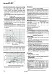
o40 o40 o32 o25 o32 o25 o20 o20 o40 o32 o25 o20 20 25 32 40 0.26 0.42 0.67 1.19 50 100 300 500 0 50 100 200 300 400 500 20 10 30 40 50 60 0 500 1000 0.1 0.2 0.3 0.4 0.5 20 25 32 40 196 313 443 784 . When selecting cylinders, refer to the Precautions and allowable kinetic energy when locking on page 702, and then select a cylinder. 20 CNG-L020 CNG-F020 CG-T020 CG-D020 CNG-020-24 CG-020-24A 25 CNG-L025 CNG-F025 CG-T025 CG-D025 CNG-025-24 CG-025-24A 32 CNG-L032 CNG-F032 CG-T032 CG-D032 CNG-032-24 CG-032-24A 40 CNG-L040 CNG-F040 CG-T040 CG-D040 CNG-040-24 CG-040-24A Caution/Allowable Kinetic Energy when Locking 1. In terms of specific load conditions, the allowable kinetic energy indicated in the table above is equivalent to a 50% load ratio at 0.5 MPa, and a piston speed of 300 mm/sec. Therefore, if the operating conditions are below these values, calculations are unnecessary. 2. Apply the following formula to obtain the kinetic energy of the load. 3. The piston speed will exceed the average speed immediately before locking. To determine the piston speed for the purpose of obtaining the kinetic energy of load, use 1.2 times the average speed as a guide. 4. The relation between the speed and the load of the respective tube bores is indicated in the diagram below. Use the cylinder in the range below the line. 5. Even within a given allowable kinetic energy level, there is an upper limit to the size of the load that can be sustained. Thus, a horizontally mounted cylinder must be operated below the solid line, and a vertically mounted cylinder must be operated below the dotted line. Ek: Kinetic energy of load (J) m: Load mass (kg) υ: Piston speed (m/s) (Average speed x 1.2 times) Allowable kinetic energy (J) Bore size (mm) Load mass (kg) Piston speed (mm/s) Bore size (mm) Holding force (N) Holding Force of Spring Locking (Maximum static load) Note) Holding force at piston rod extended side decreases approximately 15%. Holding Force of Pneumatic Locking (Maximum static load) Air pressure applied to pressurized locking port (MPa) Holding force (N) Caution when Locking Operating Precautions Caution Holding force (maximum static load) means the maximum capability of holding a static load that is not accompanied by vibration or impact under the condition that no load is applied. Therefore, it does not refer to a load that cannot be held constantly. When using (selecting) this product, carefully check the following points. . If the piston rod slips because the lock’s holding force has been exceeded, the brake shoe could be damaged, resulting in a reduced holding force or shortened life. . The upper limit of the load that is used under the conditions not associated with the kinetic energy when locking, such as drop prevention must be 35% or less of the holding force. . Do not use the cylinder in the locked state to sustain a load that involves impact. 1. Do not operate the cushion valve in the fully closed or fully opened state. Using it in the fully closed state will cause the cushion seal to be damaged. Using it in the fully opened state will cause the piston rod assembly or the cover to be damaged. 2. Operate within the specified cylinder speed. Otherwise, cylinder and seal damage may occur. 3. Carefully check the cushion performance in a low speed range. The performance and effect at around 50 mm/s may vary depending on the individual difference of each product. 4. If a cylinder is actuated at high speed when mounted with one side fastened and one side free (basic type, flange type, direct mount type), the bending moment may act on the cylinder due to vibration at the stroke end, causing damage to the cylinder. In such cases, install a mounting bracket to suppress vibration of the cylinder body, or reduce piston speed until the cylinder body does not vibrate at the stroke end. Also, use a mounting bracket when moving the cylinder body, or mounting a long stroke cylinder horizontally with one-sided fastening. Stopping Accuracy (Not including tolerance of control system.) Locking method Spring locking (Exhaust locking) Pneumatic locking (Pressure locking) Spring and pneumatic locking Piston speed (mm/s) ±0.2 ±0.3 ±0.5 ±1.5 ±0.4 ±0.5 ±1.0 ±2.0 Condition/load: 25% of thrust force at 0.5 MPa Solenoid valve: Mounted to the lock port Selection/Recommended Pneumatic Circuit/Caution on Handling Caution Warning 1. Install a rod boot without twisting. If the cylinder is installed with its bellows twisted, it could damage the bellows. 2. Tighten clevis bracket mounting bolts with the following proper tightening torque. o20: 1.5N・m, o25 to 32: 2.9N・m, o40: 4.9N・m, o50: 11.8N・m, o63 to 80: 24.5N・m, o100: 42.2N・m Caution For detailed speceifications of the fine lock cylinder, Series CLG1 mentioned above, refer to pages 702 to 705. Mounting Bracket Part No. Bore size (mm) Mounting blacket Axial foot . Flange Trunnion pin Clevis .. Rod side pivot bracket Head side pivot bracket . When ordering foot bracket, order 2 pieces per cylinder. .. For the clevis style, clevis pins, retaining rings and mounting bolts are included. ... Mounting bolts are shipped together for the foot and flange styles. (mm) 736 Series CLG1