3-p0701-0768-cl_en 42 / 69
10秒後にBOOKのページに移動します
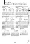
o o o o o o o o L L1 L L1 o . o o I-G02/G03 Material: Rolled steel I-G04 Material: Cast iron Y-G02/G03 Material: Rolled steel Y-G04 Material: Cast iron o o x x Knock pin hole Knock pin hole o20 to o40 Material: Rolled steel o20 to o40 Material: Rolled steel Material: Carbon steel Material: Carbon steel Material: Carbon steel (Hole dia.) o Part no. RR1 I-G02 I-G03 I-G04 20 25, 32 40 34 41 42 𡱖16 𡱖20 o22 𡱖16 𡱖20 o22 8.5 10.5 14 M8 x 1.25 M10 x 1.25 M14 x 1.5 10.3 12.8 12 11.5 14 14 +0.058 0 .0.2 8 8 .0.4 .0.2 10 .0.4 .0.3 18 .0.5 +0.058 10 0 +0.058 10 0 A Applicable bore size (mm) MM R1 U1 NDH10 NX 20 25, 32 40 34 41 42 8.5 10.5 16 25 30 30 M8 x 1.25 M10 x 1.25 M14 x 1.5 10.3 12.8 12 11.5 14 14 21 25.6 41.6 16 20 36 Y-G02 Y-G03 Y-G04 +0.058 8 0 +0.058 10 0 +0.058 10 0 +0.4 8 +0.2 +0.4 10 +0.2 +0.5 18 +0.3 NDH10 Part no. Applicable bore size (mm) A A1 E1 L1 MM U1 NX NZ L IY-G02 IY-G03 IY-G04 Applicable pin part no. A1 E1 L1 25 30 30 R Part no. Part no. CNG-020-24 CNG-025-24 CNG-032-24 CNG-040-24 CNG-020-24 CNG-025-24 CNG-032-24 CNG-040-24 CG-020-24A CG-025-24A CG-032-24A CG-040-24A CG-020-24A CG-025-24A CG-032-24A CG-040-24A 20 25 32 40 20 25 32 40 13 15 17 21 3.2 3.2 4.5 4.5 21.2 21.3 25.6 26.3 47.8 54.8 57.4 65.4 42 42 48 56 26 28 28 36 28 28 28 30 50 57 61.4 71.4 42 48 53 60 10 10 10 10 20 25 32 40 20 25 32 40 13 15 17 21 3.2 3.2 4.5 4.5 18.1 20.7 23.6 27.3 35.8 39.8 49.4 58.4 42 42 48 56 16 20 22 30 28 28 28 30 38.3 42.1 53.8 64.6 36 43 50 58 10 10 10 10 5.5 5.5 6.6 6.6 25 30 35 40 (29.3) (33.1) (40.4) (49.2) 5.5 5.5 6.6 6.6 31 37 38.5 42.5 +0.036 8 0 40 8 47 47 55 +0.036 10 0 10 +0.043 12 0 12 +0.043 14 0 14 Applicable bore size (mm) Applicable bore size (mm) Applicable bore size (mm) Applicable bore size (mm) TB TdH9 TR TT TU TV TW TX TY TZ TE TF TH Part no. Part no. TN TB Td TR TT TU TV TW TX TY TZ TE TF TH TN .0.040 .0.076 8 .0.040 10 .0.076 .0.050 12 .0.093 .0.050 14 .0.093 Applicable bore size (mm) Part no. Part no. Applicable bore size (mm) B C D d H NT-02 NT-03 NT-G04 20 25, 32 40 13 17 19 15.0 19.6 21.9 12.5 16.5 18 M8 x 1.25 M10 x 1.25 M14 x 1.5 5 6 8 Part no. IY-G02 IY-G03 IY-G04 20 25, 32 40 21 25.6 41.6 7.6 9.6 9.6 16.2 20.2 36.2 1.5 1.55 1.55 0.9 1.15 1.15 Type C 8 for axis Type C 10 for axis Type C 10 for axis Dd9 Applicable bore size (mm) L d L1 m t Dd9 L d L1 Applicable retaining ring Applicable m t retaining ring CD-G02 CD-G25 CD-G03 CD-G04 2 0 25 32 40 43.4 48 59.4 71.4 7.6 9.6 11.5 13.4 38.6 42.6 54 65 1.5 1.55 1.55 2.05 0.9 1.15 1.15 1.15 Type C 8 for axis Type C 10 for axis Type C 12 for axis Type C 14 for axis .0.040 .0.076 8 .0.040 10.0.076 .0.040 10.0.076 . Retaining rings are included. . Retaining rings are included. Rod Side Pivot Bracket Head Side Pivot Bracket Knuckle Pin Clevis Pin Rod End Nut Single Knuckle Joint Double Knuckle Joint . Knuckle pin and retaining ring are packaged. Series CLG1 Accessory Bracket Dimensions 741 CLJ2 CLM2 CLG1 CL1 MLGC CNG MNB CNA2 CNS CLS CLQ RLQ MLU MLGP ML1C D-𡱖 -X𡱖