3-p0701-0768-cl_en@@@47 / 69
10bÐèBOOKäy[WèÖÛçÉñ
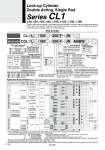
40 50 63 40 mm 50 mm 63 mm 80 mm 100 mm 125 mm 140 mm 160 mm Symbol Bore size Symbol Bore size Symbol Bore size 80 100 125 140 160 CL1 With auto switch CDL1 L L 200 200 Cylinder tube I.D. Nil S n 2 pcs. 1 pc. gnh pcs. Rod boot Cushion Nil J K N R H Nil JN JN 100 100 F F BLFG CDT F B M9BW Nil Nil TN TF Rc NPT G DC AC PLC o40 to o100 o125 to o160 A33C... A34C... A44C... G39C K39C P4DW... o40 to o100 o125 to o160 5 V 100 V 100 V or less 100 V, 200 V 100 V, 200 V 200 V or less 100 V, 200 V 12 V 5 V,12 V 12 V 12 V 12 V 5 V,12 V 12 V 5 V, 12 V 5 V, 12 V 24 V DIN terminal 24 V 24 V How to Order With auto switch (Built-in magnet) Made to Order Refer to page 745 for details. Number of auto switches Auto switch . For the applicable auto switch model, refer to the table below. Without auto switch With rod boot/cushion Without rod boot Nylon tarpaulin Heat resistant tarpaulin Without cushion With rod cushion With head cushion With cushion on both ends . Indicate alphabetically when 2 or more symbols are applicable. Built-in Magnet Cylinder Model If a built-in magnet cylinder without an auto switch is required, there is no need to enter the symbol for the auto switch. (Example) CDL1L40-100F Locked-up direction . For both sides lock, refer to Made to Order g-X51h. Piston extension locking Piston retraction locking Port thread type Cylinder stroke (mm) For details, refer to page 745. Mounting style Basic style Foot style Rod side flange style Head side flange style Single clevis style Double clevis style Center trunnion style Tubing material .1 Auto switches are not available with steel tube. Applicable Auto Switches/Refer to pages 1893 to 2007 for further information on auto switches. Type Special function Electrical entry Indicator light Wiring (Output) Load voltage Auto switch model Tie-rod mounting Band mounting 3 (L) 1 (M) 5 (Z) Lead wire length (m) Applicable load Pre-wired 0.5 connector (Nil) Relay, PLC Relay, PLC Relay, PLC IC circuit IC circuit IC circuit IC circuit IC circuit 3-wire (NPN) 3-wire (NPN) 3-wire (PNP) 2-wire 3-wire (NPN) 3-wire (NPN) 4-wire (NPN) 3-wire (PNP) 3-wire (PNP) 2-wire 2-wire 2-wire (Non-polar) 2-wire 2-wire 3-wire (NPN equivalent) Yes No Yes No Yes Yes Grommet Grommet Grommet Grommet Terminal connector Terminal connector Reed auto switch Solid state auto switch Diagnostic indication (2-color indication) Diagnostic indication (2-color indication) Water resistant (2-color indication) With diagnostic output (2-color indication) Magnetic field resistant (2-color indication) . Lead wire length symbols: 0.5 m EEEEEEENil (Example) M9NW 1 m EEEEEEEM (Example) M9NWM 3 m EEEEEEE L (Example) M9NWL 5 m EEEEEEE Z (Example) M9NWZ . Solid state auto switches marked with g h are produced upon receipt of order. .. D-A9ÞÙ/A9ÞÙV cannot be mounted on o50. ... The following auto switches cannot be mounted on o125 to o160. D-G39C, K39C, A3ÞÙC, A44C, G5ÞÙ, K59, G5ÞÙW, K59W, G5BA, G59F, G5NT, B5ÞÙ, B64, B59W, P4DW. .1 Water resistant type auto switches can be mounted on the above models, but in such case SMC cannot guarantee water resistance. Consult with SMC regarding water resistant types with the above model numbers. . Since there are other applicable auto switches than listed, refer to page 766 for details. . For details about auto switches with pre-wired connector, refer to pages 1960 and 1961. . D-A9ÞÙ/M9ÞÙ/M9ÞÙW/M9ÞÙA auto switches are shipped together (not assembled). (Only auto switch mounting brackets for the models listed above are assembled at the time of shipment.) Symbol Bore size 40 to 100 125,140 160 40 to 160 Without magnet Tubing material Aluminum tube Aluminum tube (1000st or less) Steel tube (1001st or more) Aluminum tube (1200st or less) Steel tube (1201st or more) Steel tube Built-in magnet Tubing material Nil Aluminum tube F .1 G59... G5P... K59... K59... G5PW... K59W... G5BA... G59F... B54... B64... B59W... G39 K39 A33 A34 A44 M9N M9P M9B J51 M9NW M9PW M9BW M9NA.1 M9PA.1 M9BA.1 F59F A96.. A93.. A90.. A54 A64 A59W 746 The CL1 series lock-up cylinder is a self-locking type that contains a ring that is tilted by a spring force, which is further tilted by the load that is applied to the cylinder, thus locking the piston rod. This cylinder is suitable for intermediate stops, emergency stops, or for drop prevention. Lock-up Cylinder Double Acting, Single Rod Series CL1 o40, o50, o63, o80, o100, o125, o140, o160 A