3-p0701-0768-cl_enü@ü@ü@48 / 69
10ĢbīŃé╔BOOKé╠āyü[āWé╔ł┌ō«éĄé▄éĘ
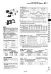
-XAŁ -XC3 -XC14 Change of rod end shape Special port location Change of trunnion bracket mounting position (o40 to 100 only) Symbol Specifications -X50 -X51 Large bore lock-up cylinder (o180 to o300) Both-directions lock-up cylinder Symbol Specifications Lock operation Spring lock Specifications Bore size (mm) o40 to o100 1.5 MPa 1.0 MPa o125 to o160 1.57 MPa 0.97 MPa 0.08 MPa 50 to 200 mm/s Not required (Non-lube) Air cushion Up to 250+1.0, 251 to 1000+1.4, 1001 to 1500+1.81501 to 1600+2.2 Basic style , Axial foot style, Rod side flange style Head side flange style, Single clevis style Double clevis style, Center trunnion style Max. Load and Lock Holding Force (Max. static load) Bore size (mm) 40 588 294 1230 50 981 490 1920 63 1470 735 3060 80 2450 1230 4930 100 3820 1910 7700 125 6010 3000 12100 140 7540 3770 15100 160 9850 4920 19700 Lock-up Unit Specifications 50 mm/s 100 mm/s 200 mm/s Piston speed Bore size (mm) 40 to 100 0.6 mm 1.2 mm 2.3 mm 125 to 160 1 mm 2 mm 3 mm Lock-up Unit Model 40 CL-40 50 CL-50 63 CL-63 80 CL-80 100 CL-100 Cylinder Stroke (o40 to o100) / Bore size (mm) 40 50, 63 80, 100 Standard stroke (mm) Long stroke (L, F only) Holding force (Max. static load) (N) 25, 50, 75, 100, 125, 150, 175, 200, 250, 300, 350, 400, 450, 500 25, 50, 75, 100, 125, 150, 175, 200, 250, 300, 350, 400, 450, 500, 600 25, 50, 75, 100, 125, 150, 175, 200, 250, 300, 350, 400, 450, 500, 600, 700 800 1200 o80: 1400, o100: 1500 125, 140 160 Cylinder Stroke (o125 to o160) Tube material Aluminum alloy Carbon steel piping Up to 1000 Up to 1200 Unit: mm Unit: mm Up to 1000 Up to 1200 Up to 1600 Up to 1600 Basic style, Head side flange style, Single clevis style,Double clevis style, Center trunnion style, Foot style, Rod side flange style Basic style, Head side flange style, Single clevis style,Double clevis style, Center trunnion style, Basic style, Head side flange style, Single clevis style,Double clevis style, Center trunnion style, Foot style, Rod side flange style Foot style, Rod side flange style 125, 140 160 Cylinder Stroke/ Cylinder with Auto Switch (Built-in magnet) Up to 1000 Up to 1200 Up to 1400 Up to 1400 Refer to the minimum auto switch mounting stroke (pages 760 and 762) for those with an auto switch. Refer to the minimum auto switch mounting stroke (pages 760 and 762) for those with an auto switch. +. +. +. +. +. +. Refer to pages 760 to 766 for cylinders with auto switches. . Minimum auto switch mounting stroke . Proper auto switch mounting position (detection at stroke end) and mounting height . Operating range . Switch mounting bracket: Part no. 0.2 MPa or more (at no load) 0.05 MPa or less Lock-up release pressure Lock-up start pressure Lock-up direction One direction (Lock direction can be changed.) Stopping Accuracy (Not including tolerance of control system) Applicable bore size (mm) Lock-up unit part no. Bore size (mm) Bore size (mm) . Proof pressure Maximum operating pressure Minimum operating pressure Piston speed Ambient and fluid temperature Lubrication Cushion Stroke length tolerance Mounting Without auto switch .10 to 70 C With auto switch .10 to 60 C (No freezing) Without auto switch 0 to 70 C With auto switch 0 to 60 C (No freezing) . Make sure to operate the cylinder in such a way that the piston speed does not exceed 200 mm/s during locking. . The maximum speed of 500 mm/s can be accommodated if the piston is to be locked in the stationary state for the purpose of drop prevention. Max. load (N) Horizontal Mounting Vertical Mounting . . The holding force (max. static load) indicates the maximum capability to hold a static load without loads, vibration or impact. This does not indicate a load that can be held in ordinary conditions. The maximum load is limited depending on the mounting orientation. Refer to the Series CL Specific Product Precautions 1 on page 702 for selecting cylinders. Note 1) Strokes other than listed above are produced upon receipt of order. Spacers are not used for intermediate strokes. Note 2) Long strokes are applicable for the axial foot and rod side flange styles. If other mounting brackets are used or the length exceeds the long stroke limit, the maximum stroke should be determined based on the stroke selection table (technical data). Made to Order: Individual Specifications (For details, refer to pages 767 to 768.) Made to Order Specifications (For details, refer to pages 2009 to 2152.) 747 Series CL1 Lock-up Cylinder Double Acting, Single Rod CLJ2 CLM2 CLG1 CL1 MLGC CNG MNB CNA2 CNS CLS CLQ RLQ MLU MLGP ML1C D-« -X«