3-p0701-0768-cl_en 50 / 69
10秒後にBOOKのページに移動します
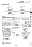
o40 to o100 o125 to o160 Construction Principle Caution on Changing the Lock-up Direction Caution Unlocked state Locked-up state Air pressure supply Spring Piston rod operating direction Piston rod operating direction Locked-up ring Release piston Air pressure exhaust Air pressure supply Tie-rod Air pressure supply Lock-up unit Air pressure supply Cap bolt Retainer End boss Caution 3. Turn the unit to the opposite end so that the end without the scraper is facing the cylinder rod cover. Then, securely insert the unit into the end boss portion of the rod cover. 4. Install four tie-rods, with their shorter threaded portion oriented towards the rod cover, and tighten them with uniform torque. Until the installation and adjustment have been completed, never pull out the unlocking bolt (or release the air pressure). The processes described above complete the changing of the locked-up direction. Before using the cylinder, make sure that the lock-up operates properly. 1. Loosen the tie-rod nuts and pull out the four tie-rods. 2. Apply air pressure of 0.2 MPa to 0.3 MPa to disengage the lock and pull out the lock-up unit from the piston rod. 3. Remove the retainer plate from the lock-up unit and install the retainer plate on the opposite end. Reapply the air pressure, and with the end on which the retainer plate had, until now, been facing towards the cylinder, insert the locked-up unit into the piston rod and fit it into the end boss portion of the rod cover. 4. Install the four tie-rods, with their shorter threaded portion oriented towards the rod cover, and tighten them with uniform torque. Maintain the application of air pressure until the installation and adjustment have been completed, and never actuate the lock in the meantime. When the lock-up unit is not secured by the tie-rods, the air pressure applied to the lock-up port should be between 0.2 MPa and 0.3 MPa. Never supply a higher air pressure as it could lead to equipment damage. The lock-up is unidirectional. However, the lock-up direction can be changed easily. To change the direction, pay particular attention to the following steps: Loosening the tie-rods for the purpose of changing the direction could also loosen the nuts on the cylinder side. Therefore, before assembling the unit, make sure to verify that the nuts on the cylinder are not loose. Retighten the nuts if they are loose, and while turning the piston rod, apply a low pressure of 0.08 MPa to make sure that it operates smoothly in both the extending and retracting directions. 1. Loosen the tie-rod nuts and pull out the four tie-rods. 2. Open the rubber cap and screw in the unlocking bolt, which is provided as an accessory part. At this time, apply air pressure of 0.2 MPa to 0.3 MPa to disengage the lock and insert the bolt. (The operation to follow can be performed properly and easily with the application of air pressure.) After verifying that the bolt has been inserted properly, pull out the unit from the rod. Then, loosen the three screws in the scraper presser plate to remove the presser plate and the scraper. Install the scraper and the presser plate, in that order, on the opposite side. 749 Series CL1 Lock-up Cylinder Double Acting, Single Rod CLJ2 CLM2 CLG1 CL1 MLGC CNG MNB CNA2 CNS CLS CLQ RLQ MLU MLGP ML1C D- -X